
Owner manual


P/N64118rev.B
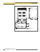
Control Module Configuration
18
Banner Engineering Corp. •Minneapolis,U.S.A.
www.bannerengineering.com•Tel:763.544.3164
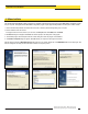
5.1.2 Factory Settings
Ofthe15availablecontrolmoduleIDvalues(‘A’through‘O’),thefactorysoftware
settingisA.Selectablecommunicationbaudratesare9600,19200,and38400;the
factorysettingis9600.Seesection5.3.1forinformationonchangingthesesettings.
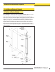
5.2 System Alignment
Theemitter/receiverpairshaveawidefieldofviewandareeasytoalign.The
recommendeddistancebetweentheemitterandreceiverrangesfrom15"to72".
(Shortersensorseparationcanbeachieved;pleaseconsultfactoryfordetails.)The
AlignmentprocessshouldbeperformedatSysteminstallationandrepeatedeverytime
oneorbothofthesensorsismoved.AlignmentoftheSystemcanbespecified
automaticallyusingeithertheAlignmentroutineoftheconfigurationsoftwareorthe
Alignmentswitchonthecontrolmodule’sfrontpanel.
TheSystemalsomaybealignedremotely,usingpins14and15ontheterminalblock.
Apply10to30Vdcpowertothepins(seepage14)toapproximatethepush-button
procedure.(Forexample,applyinputsignalfor3secondstoaccessAlignmentmode.)
Makesurethesensorshavebeenwiredasshowninsection3.3.Applypowertothe
controlmoduleviaterminals#1and#2(16to30Vdc).TheDiagnosticsIndicatorwill
showthesensorsgoingthoughapower-uptest:firstthereceiver,thentheemitter.
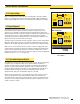
AfterthesensorshavebeentestedandtheSystemisreadyforservice,theDiagnostics
Indicatorwillshow‘—’or‘—.’;seeFigure5-4.
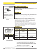
5.2.1 Push-button Alignment Routine
Atinstallationorwhenevertheemitterand/orreceiverismoved,theSystemshouldbe
re-aligned.PresstheAlignmentswitchonthecontrolmodulefrontpanelfor3
seconds,afterwhichtimetheletter‘A’willappearontheDiagnosticsIndicator;the
Systemis“learningaclearcondition.”Rotatethesensorsasrequired(butdonot
changethedistancebetweenthem).WhenthegreenAlignmentLEDisdisplayedon
thecontrolmoduleandreceiver,thesensorsareadequatelyaligned.Toleave
Alignmentmode,againpresstheAlignmentswitchfor3seconds.
Duringthealignmentprocedure,thesystempollseachreceiverchanneltomeasure
excessgainandperformsacoarsegainadjustment.Whenthesystemexitsthe
alignmentprocedure,eachchannel’ssignalstrengthisstoredinnon-volatilememory.
Thesystemisnowreadyforoperationanddoesnotrequirere-alignmentunlessthe
emitterorreceiverismoved.
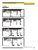
Figure 5-4. Diagnostics Indicator showing a
clear condition
HIGH RESOLUTION MINI-ARRAY CONTROLLER
ALIGNMENT
SWITCH
POWER
POWER
DIAGNOSTICS
INDICATOR
2 - TX
3 - RX
5 - COM
RS-232
MAHCN-1
OUTPUT
ALARM
GATE
ALIGN
1
+ –
+
–
16-30V dc
1A MAX
10-30VDC
GATE
30V
150mA MAX
EMTR RCVR
2 3 4 5 6 7 8 9 10 11 12 13 14 15 16 17 18 19 20
F1
NC NC NC
+12V COM DRN T/R T/R
BR BU BK WH
OUTPUT#1
TX TX
30V(MAX)
150mA MAX
ALARM
+
–
10-30VDC
ALIGN
RS-485
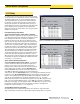
Denotes
Blanking
With Blanking OFF
With Blanking ON