
Owner manual


15
Banner Engineering Corp. •Minneapolis,U.S.A.
www.bannerengineering.com•Tel:763.544.3164
P/N64118rev.B
2 - TX
3 - RX
5 - COM
RS-232
532
Installation and Mechanical Alignment
Serial Communication
RS-232:AllA-GAGEHigh-ResolutionMINI-ARRAYSystemsmaycommunicatewitha
hostcomputerorcontrollerviaRS-232orRS-485serialprotocol.See
Section5.3.1forselectablecommunicationsparameters.PrepareanRS-232
cableusingamaleDB-9connectorwithconnectionsasshowninFigure3-8.
NOTE:DONOTusea“nullmodem”RS-232cable
RS-485: RS-485serialportislocatedatterminals#18(TX)and#19(TX).
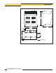
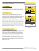
DB-9 Pin # Function
2
Transmit(TX)
3
Receive(RX)
5
Ground(GND)
3.3.1 Emitter and Receiver Hookups
Emittersandreceiversconnecttogetherinparalleltoterminals#4through#8ofthe
controlmodule(identicalforallcontrolmodulemodels).SeeFigures3-3,3-4,3-5,and
3-6forwirecolorinformation.
3.3.2 Inputs
System Power: Connectasourceof16to30Vdc,ratedat1amporgreater,tocontrol
moduleterminals#1(+)and#2(-).Connectagoodearthgroundtoterminal#3to
provideelectricalandRFnoiseimmunitytotheSystem.
NOTE:Removepowerbeforemakingotherconnectionstothecontroller.
Gate Signal: Asourceof10to30Vdcswitchedtoterminals#12(+)and#13(-)
providesagatinginput(ifrequired).Thegatingvoltagetypicallyisswitchedbythe
open-collectoroutputtransistorofadcsensingdevice.Thegatesignalcontrols
scanningwhenoneoffourGateoptionsisselectedintheControlModeSelection
menuofthePSFconfigurationroutine(seeSection5.3.2).
Align: Asourceof10to30Vdcswitchedtoterminals#14(+)and#15(-)providesa
remotemeansofrunningtheautomaticalignmentandblankingroutines.Theswitch
sequenceisidenticaltotheproceduredescribedinSection5.2.1fortheAlignment
switchonthefrontofthecontrolmodule.
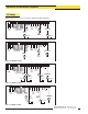
Control Module
Analog Outputs
(Terminals #10 and 16)
Discrete Outputs*
(Terminals #9 and 20)
MAHCVN-1
Figure3-3
0to10VSourcing
15mAmax.
NPNopen-collector
30Vdcmax.
150mAmax.
MAHCVP-1
Figure3-4
0to10VSourcing
15mAmax.
PNPopen-collector
30Vdcmax.
MAHCIN-1
Figure3-5
4to20mA
Sinking
16to30Vdc
NPNopen-collector
30Vdcmax.
150mAmax.
MAHCIP-1
Figure3-6
4to20mA
Sinking
16to30Vdc
PNPopen-collector
30Vdcmax.
150mAmax.
*NOTE:DiscreteOutput#2islabeled“Alarm”onthecontrolmodule.
Figure 3-8. DB-9 connections between the
control module and the PC
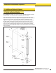
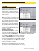
Trim braided shield flush
with cable
Trim foil shield flush
with cable
Uninsulated
drain wire
Figure 3-7. Emitter and receiver cable
preparation
Banner Engineering Corp. •Minneapolis,U.S.A.
www.bannerengineering.com•Tel:763.544.3164
NOTE:The“drainwire”istheuninsulated
strandedwirewhichrunsbetweenthe
braidedshieldandthefoilshield.Thefoil
shieldandthebraidedshieldshouldbe
removedatthepointwherethewiresexit
thecable.
3.3.3 Outputs