
Owner manual


13
Banner Engineering Corp. •Minneapolis,U.S.A.
www.bannerengineering.com•Tel:763.544.3164
P/N64118rev.B
NON-QD EndQD End
Min. R.
Full R (4)
4.8 mm (2)
(0.19")
38.1 mm
(1.50")
6.4 mm R
(0.25")
44.5 mm
(1.75")
6.4 mm
(0.25")
57.2 mm
(2.25")
3.8 mm
(0.15")
10.2 mm (2)
(0.40")
ø30.5 mm
(1.20")
34.8 mm
(1.37")
11.9 mm
(0.47")
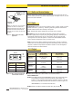
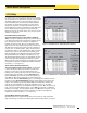
Slots have clearance
for M4 bolts (supplied)
and allow ±30° rotation
ø13.2 mm
(0.52")
ø6.8 mm (2)
(0.27")
3.0 mm
(0.12")
24.6 mm
(0.97")
53.8 mm
(2.12")
Material: Cold Rolled Steel
Finish: Black, Zinc Plated
Chromate Dip
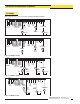
Figure 3-2. A-GAGE High-Resolution MINI-ARRAY emitter and receiver mounting bracket
dimensions
Installation and Mechanical Alignment
Banner Engineering Corp. •Minneapolis,U.S.A.
www.bannerengineering.com•Tel:763.544.3164
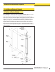
Mounttheemitterandreceiverintheirbracketsandpositiontheredlensesofthetwo
unitsdirectlyfacingeachother.Theconnectorendsofbothsensorsmustpointinthe
samedirection.Measurefromoneormorereferenceplanes(e.g.thebuildingfloor)to
thesamepoint(s)ontheemitterandreceivertoverifytheirmechanicalalignment.If
thesensorsarepositionedexactlyverticalorhorizontaltothefloor,acarpenter’slevel
isusefulforcheckingalignment.Astraightedgeorastringextendedbetweenthe
sensorsalsohelpswithpositioning.Alsocheck“byeye”forline-of-sightalignment.
Makeanynecessaryfinalmechanicaladjustments,andhand-tightenthebracket
hardware.SeeSection6forinformationonalignmentindicatorsandSection5for
informationontheuseofthealignmentsoftwarewhichissuppliedwiththecontroller.
3.2 Control Module Mounting
ThecontrolmodulemustbeinstalledinsideanenclosurewhichhasaNEMA(orIEC)
ratingsuitablefortheoperatingenvironment.
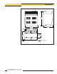
MountingdimensionsforthecontrollerareshowninFigure2-2,onpage11.The
controlmoduleissuppliedwithM3.5hardwarefordirectmountingtoasurface,orthe
modulemaybemountedontostandard35mmDINrail.