¤ A-GAGE® High-Resolution MINI-ARRAY® Instruction Manual For controllers with 2 analog and 2 discrete outputs High-Resolution MINI-ARRAY Features • Excels at high-speed, precise process monitoring and inspection applications • A comprehensive combination of scanning modes and outputs: – 10 measurement (“Scan Analysis”) modes – 3 scanning methods – Beam blanking – Selectable continuous, gated or hostcontrolled scan initiation – Programmable hysteresis for high and low limits – Serial communication optio
Banner Engineering Corp. • Minneapolis, U.S.A. 2 P/N 64118 rev. B www.bannerengineering.com • Tel: 763.544.
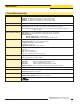
Table of Contents 1. System Description . . . . . . . . . . . . . . . . . . . . . . . . . . . . . . . . . . . . . . . . . . . 1.1 System Components . . . . . . . . . . . . . . . . . . . . . . . . . . . . . . . . . . . . . . . . . . . . . . 1.2 System Features . . . . . . . . . . . . . . . . . . . . . . . . . . . . . . . . . . . . . . . . . . . . . . . . . . 1.3 Typical Applications . . . . . . . . . . . . . . . . . . . . . . . . . . . . . . . . . . . . . . . . . . . . . . . 4 4 6 7 2. Specifications . .
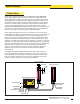
System Description 1. System Description The A-GAGE® High-Resolution MINI-ARRAY® measuring light screen is ideal for applications such as on-the-fly product sizing and profiling, edge-guiding and centerguiding, loop tensioning control, hole detection, parts counting and similar uses. 1.
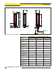
System Description Emitter and Receiver Models Emitter/Receiver Model Array Length Y* Total Beams MAHE6A Emitter MAHR6A Receiver 163 mm (6.4") 64 MAHE13A Emitter MAHR13A Receiver 325 mm (12.8") 128 MAHE19A Emitter MAHR19A Receiver 488 mm (19.2") 192 MAHE26A Emitter MAHR26A Receiver 650 mm (25.6") 256 MAHE32A Emitter MAHR32A Receiver 813 mm (32.0") 320 MAHE38A Emitter MAHR38A Receiver 975 mm (38.4") 384 MAHE45A Emitter MAHR45A Receiver 1138 mm (44.
System Description 1.2 System Features Built-in features simplify the operation of the A-GAGE High-Resolution MINI-ARRAY system. High-resolution emitters and receivers, available in 12 lengths, feature two closely spaced columns of beams to provide a precise, high-resolution light screen for exacting applications. The Alignment routine automatically equalizes the excess gain of each beam for reliable 2.5-mm (0.10") object detection throughout the array and stores this data in non-volatile memory.
System Description Supplied System Software The supplied HRMA software program, used to configure each System control module, may be run on any PC-compatible computer running Windows® . The menu-driven program walks the user through the many scanning and output options. After the desired options are selected, the user can save the combination of selections in a Parameter Setup File (PSF), and store it in the control module’s non-volatile memory.
Specifications 2. Specifications 2.1 Emitter and Receiver Specifications Emitter/Receiver Range 380 mm to 1.8 m (15" to 6') Minimum Object Sensitivity 2.5 mm (0.1") Sensor Scan Time 1.8 milliseconds to 58.4 milliseconds, depending on scanning method and sensor length; see Section 5.3.
Specifications With mounting bracket flanges “out” With mounting bracket flanges “in” 53.8 mm (2.12") L1 38.1 mm Square (1.50") L3 L2 2.5 mm (0.10") 47.2 mm (1.86") 18.3 mm (0.72") 10.2 mm (0.40") 71 mm (2.8") R13 mm (0.5") Minimum Bend Figure 2-1. Emitter and receiver dimensions Emitter/Receiver Model Housing Length Distance Between Bracket Holes L1 L2 L3 MAHE6A Emitter MAHR6A Receiver 236 mm (9.3") 268 mm (10.5") 211 mm (8.3") MAHE13A Emitter MAHR13A Receiver 399 mm (15.
Specifications 2.2 Control Module Specifications Output Configuration MAHCVP-1: Two PNP discrete (switched), two 0-10V voltage sourcing MAHCVN-1: Two NPN discrete (switched), two 0-10V voltage sourcing MAHCIP-1: Two PNP discrete (switched), two 4-20 mA current sinking MAHCIN-1: Two NPN discrete (switched), two 4-20 mA current sinking Power Requirements 16 to 30V dc @ 1.0 A (typical: 0.5 A @ 16V dc) Inputs Sensor input: Emitter and receiver wire in parallel to five terminals.
Specifications 115.0 mm (4.53") 106.0 mm (4.17") 5.0 mm (0.20") 81.0 mm (3.19") 96.0 mm (3.78") 69.0 mm (2.72 ") 5.5 mm (0.22") 35.0 mm (1.38") DIN mounting slot Slot for M3.5 screws (2) Figure 2-2. Control module dimensions Banner Engineering Corp. • Minneapolis, U.S.A. www.bannerengineering.com • Tel: 763.544.3164 P/N 64118 rev.
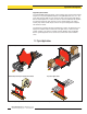
Installation and Mechanical Alignment 3. Installation and Mechanical Alignment 3.1 Emitter and Receiver Mounting Banner MINI-ARRAY emitters and receivers are small, lightweight, and easy to handle during mounting. The mounting brackets (supplied) allow ±30° rotation. From a common point of reference, make measurements to locate the emitter and receiver in the same plane with their midpoints directly opposite each other.
Installation and Mechanical Alignment Mount the emitter and receiver in their brackets and position the red lenses of the two units directly facing each other. The connector ends of both sensors must point in the same direction. Measure from one or more reference planes (e.g. the building floor) to the same point(s) on the emitter and receiver to verify their mechanical alignment.
Installation and Mechanical Alignment 3.3 Hookups Refer to Figures 3-4, 3-5, 3-6, and 3-7 for the appropriate hookup information.
Installation and Mechanical Alignment 3.3.1 Emitter and Receiver Hookups Trim braided shield flush with cable Trim foil shield flush with cable Emitters and receivers connect together in parallel to terminals #4 through #8 of the control module (identical for all control module models). See Figures 3-3, 3-4, 3-5, and 3-6 for wire color information. Uninsulated drain wire 3.3.2 Inputs NOTE: The “drain wire” is the uninsulated stranded wire which runs between the braided shield and the foil shield.
Software Installation 4. Software Installation The High-Resolution MINI-ARRAY software CD includes an installation routine that quickly and easily loads the MINI-ARRAY configuration program into your computer. The High-Resolution MINI-ARRAY configuration program requires approximately 50 MB of hard disk space. Install as follows: 1. Use the Parameter Setup Software CD included with the controller, or download (www.bannerengineering.com) as required. 2. Insert the Software CD into the CD drive.
Control Module Configuration 5. Control Module Configuration The A-GAGE High-Resolution MINI-ARRAY control module is easily configured using a Windows® menu-style routine; the configuration routine requires the Banner-supplied HRMA software and a PC-compatible computer (running Windows® XP, Vista, or 7) A serial data connection is made between the computer and the DB9 connector on the control module. Figure 5-1. Options menu, serial port selection 5.
HIGH RESOLUTION MINI-ARRAY CONTROLLER POWER 1 2 Control Module Configuration 3 4 5 6 7 F1 BR BU + 9 10 11 12 13 14 15 16 17 18 1 NC OUTPUT#1 16-30V dc 1A MAX EMTR 30V 150mA MAX RCVR OUTPUT DIAGNOSTICS 8 9 F1 POWER BR BU NC 16-30V dc The emitter/receiver pairs have a wide field of view and are easy to align. The 1A MAX With Blanking ON recommended distance between the emitter and receiver ranges from 15" to 72".
Control Module Configuration 5.2.2 Software Alignment Routine The green LED indicator on the receiver and also on the control module continuously displays Alignment status. When all unblanked beams are clear, the green Alignment indicators will be ON. To better understand blocked, clear and blanked beams, launch the Alignment routine (press F8 or select Alignment under the MINI-ARRAY menu). The screen will show the state of all of the beam channels, grouped into sets of 16.
Control Module Configuration 5.2.3 Blanking If a machine fixture or other equipment will continuously block one or more beams, the affected beam channels may be blanked. The Blanking option causes the control module to ignore the status of blanked beams for measurement mode calculations. For example, if a machine fixture blocks one or more beams during System operation, the output data will be incorrect; if beams blocked by the fixture are blanked, the output data will be correct.
Control Module Configuration To accommodate parts or components that will move through the array, blanking may be manually adjusted for one or more individual beam channels. After using the System software to specify blanking, select ‘Edit’ from the Alignment screen; the Diagnostics Indicator will continue to show the letter ‘b’ and a grid will appear on the computer screen (Figure 5-8). The beams are numbered from the sensors’ cabled ends, with the beam closest to the cable being beam #1.
Control Module Configuration Selected Controller Identifies the specific control module being configured. Control Mode Selection Analysis (Measurement) Mode Selection Choose the measurement option that best tells you the size and/or position of objects as they relate to the array. Serial Communication Changes the identification and baud rate of the controller being configured. Serial Transmission Specifies the type of data transmitted from the control module to its host after each scan.
Control Module Configuration 5.3.1 Selected Controller and Serial Communication The Selected Controller box displays information about the control module being configured. Two of these settings may be changed in the Serial Communication box. The settings selected and displayed in these boxes are those used to identify the control module during the Ping routine (section 5.1.1). Figure 5-10.
Control Module Configuration 5.3.3 Scanning Method The control module may be configured for one of three scanning methods (Figure 5-12): • Straight scan • Single-Edge scan • Double-Edge scan Straight Scan is the default mode in which all beams are scanned in sequence from the bottom end (cable end) to the top end of the array. This scanning method requires the longest scan times and provides the smallest object detection size (2.5 mm, 0.1" diameter). Figure 5-12.
Control Module Configuration Double-Edge Scan is used to detect two edges of a single object, for example, box width measurements. Double-Edge Scan requires the selection of a step size: 2, 4, 8, 16 or 32 beams. The sensor uses the steps to “skip” over beams. Double-Edge Scan works as follows: 1. The sensor activates beam #1 (the beam closest to the sensor cable end). 2. The sensor activates the next beam, determined by the step size.
Control Module Configuration 5.3.4 Scan Analysis Mode Selection The control module may be programmed, if desired, for any one or two of seven Scan Analysis (measurement) Modes. Each selected mode may be assigned individually to an output (see section 5.3.5 or 5.3.6). The beams in the array are numbered in sequence, with beam #1 located at the cabled end of the emitter and the receiver. “Beam Location” Modes • First Beam Blocked (FBB): The control module identifies the location of the First Beam Blocked.
Control Module Configuration NOTE: When in the Null/Span screen, the controller will have a diagnostic code of 8. The Null/Span Configuration screen (Figure 5-19), may be used to adjust the zero and full scale reading for either analog output. To display the Null/Span Configuration screen, click on the Null/Span button at the bottom of the PSF Configuration screen (Figure 5-9). Each output is independent and must be adjusted separately.
Control Module Configuration 5.3.7 Discrete Output Configuration (Analysis Mode Assignment) Discrete outputs #1 and #2 (“Alarm”) may each be individually assigned to one of the Scan Analysis Modes programmed in section 5.3.4 (see Figures 5-16 and 5-22). Next to each discrete output assignment menu are Low and High Set Point boxes. The number in each box identifies a beam in the array (beam #1 being closest to the cabled end of the emitter and the receiver).
Control Module Configuration 5.4 Serial Communication with a Host Controller The control module communicates with a host process controller via RS-232 or RS-485 protocol and at the baud rate specified in the Serial Communications box (section 5.3.1). The System provides a number of data transmission options. 5.4.1 Serial Data Transmission The serial transmission portion of the PSF Configuration screen activates the serial port(s), specifies the data format, and provides data suppression options.
Control Module Configuration 5.4.3 Serial Options The Serial Options box provides two options: Suppress Clear Data and Suppress Header. Suppress Clear Data provides one method to reduce the amount of data being transmitted by the control module, accomplished by not sending data when no object is detected. The control module transmits serial data only when one or more unblanked beams of the light screen array are blocked.
System Diagnostics 5.5.1 Saving and Recalling PSF Files Figure 5-27. FileSave subscreen of the PSF Configuration screen, accessed with the File Save PSF command To place the displayed PSF into a file that can be retrieved at any time, select File Save PSF (Figure 5-26). When asked if you want to save the PSF to a file, select Yes. A subscreen titled FileSave will appear (Figure 5-27). Overtype ‘*.psf’ in the File Name entry box with the name of the file to be stored (up to 8 characters), plus the .
System Diagnostics 6. System Diagnostics System diagnostics may be performed using the status and diagnostics indicators on the control module and sensors, or by using the Diagnostics software routine, or a combination of the two. 6.1 Diagnostics Indicators NOTE: Status indicators appear to “freeze” if the controller has been configured for Gate or Host mode (Section 5.3.2), and no signal is present to cause a scan update.
System Diagnostics Diagnostics Indicator: This bright, segmented LED display on the control module front panel indicates one of 10 System status conditions, plus the presence or absence of blanking. (Blanking ON causes a period to appear in the Diagnostics Indicator window, in addition to the System’s other status condition.) See Figure 6-2 for the key to these error types and status conditions; this chart is also located on the side of the control module.
Appendix A: Data Transmission Appendix A: Data Transmission A.1 Host Mode Command String As discussed in section 5.3.2 of this manual, the control module has three control mode options: continuous, gate, and host. Host mode requires a serial transmission string from a separate device, typically a PC or process controller. The serial transmission medium can be either RS-485 or RS-232. When Host control mode is selected, the host process controller initiates scans using a command string.
Appendix A: Data Transmission Definitions for ASCII Data Values A.2.1 ASCII Format Data Transmission For the ALL measurement mode Character Ch 4 Ch3 Ch2 Ch1 F 1 1 1 1 E 1 1 1 0 D 1 1 0 1 C 1 1 0 0 B 1 0 1 1 A 1 0 1 0 9 1 0 0 1 8 1 0 0 0 7 0 1 1 1 6 0 1 1 0 5 0 1 0 1 4 0 1 0 0 3 0 0 1 1 2 0 0 1 0 1 0 0 0 1 0 0 0 0 Figure A-2. ASCII data values 0 There are two ways to use ASCII format to represent data.
Appendix A: Data Transmission For Measurement mode analysis, the binary format uses two data bytes for each measurement mode. (If we have one measurement mode, then there are two data bytes. For two measurement modes, there are four data bytes.) For example, assume that control module ‘B’ is configured for one measurement mode (FBB), and the value is 78. The string from the control module is as follows: 0x1c, ‘B’, 0x00, 0x4E, 0x0A.
Banner Engineering Corp. • Minneapolis, U.S.A. www.bannerengineering.com • Tel: 763.544.3164 P/N 64118 rev.
Appendix B: Glossary Appendix B: Glossary Blanked Beam: A beam that is “ignored” by the receiver, as a result of a blanking program being applied to it. Beams (or groups of beams) are blanked when a component or fixture will remain in or move through the light screen array; blanking the affected beams prevents the component or fixture from causing false outputs. Blocked Beam: A beam that is obstructed between the emitter and the receiver, and is not blanked.
Banner Engineering Corp. • Minneapolis, U.S.A. www.bannerengineering.com • Tel: 763.544.3164 P/N 64118 rev.
Banner Engineering Corp Limited Warranty Banner Engineering Corp. warrants its products to be free from defects in material and workmanship for one year following the date of shipment. Banner Engineering Corp. will repair or replace, free of charge, any product of its manufacture which, at the time it is returned to the factory, is found to have been defective during the warranty period.