
Cut Sheet
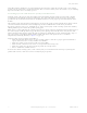

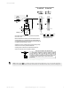


Switching Diagrams
Contact Configuration (Guard Closed State)
SI-LS83PBD SI-LS83PBE
Contacts: Open Closed Transition
Switching Diagram tolerances:
Operating point ± 0.25 mm
Operating force ± 10%
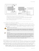
Guard closed (home position) is at 0 mm when mounted in a positive
mode. Not to scale.
Maximum allowable travel varies by model and is listed at bottom of
switching diagram (minus operating tolerance).
Installation must ensure sufficient travel for positive opening of safety
contacts and account for any mechanical tolerances.
16
4
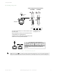
CAM
Preferred direction
of actuation
23
M5(X2)
Safety
Safety
Safety
Non-Safety
0mm
0.8
1.6
4
11 - 12
23 - 24
2.5N
10N
0mm
0.5
1.3
4
11 - 12
21 - 22
2.5N
9N
α α
β β
0.1 m/s
0.5 m/s
1 m/s
2 m/s
5 m/s
α
30°
5°
-
-
-
β
20°
20°
10°
5°
-
Max. Approach speed vs. Max. Approach angle
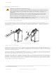
Preferable direction of actuation is parallel to the plunger axis (α°).
Exceeding specified approach angle or speed can reduce life
expectancy.
Figure 1. SI-LS83PBx Switching Diagrams
NOTE: This symbol
for a positive-opening safety contact (IEC 60947-5-1) is used in the switching
diagram to identify the point in actuator travel where the normally-closed safety contact is fully open.
Safety Limit Switches
P/N 182191 Rev. A www.bannerengineering.com - Tel: +1-763-544-3164 5