
Cut Sheet


Safety limit switches should not be used in environments that subject the switch, the actuating system, or the actuator
(cam) to extreme temperatures and vibration/shock or where excessive moisture (water, oils, coolants, etc.) or machining
chips/swarf and dust can be reasonably expected.
Actuating System and Actuator (Cam) Considerations
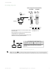
Actuating systems and actuators must be installed per the dimensioning diagram and the movement of the actuating
system must remain within the specified operating range. The slope of the actuator (cam) must not be greater than
specified and the construction material must be of sufficient hardness to ensure proper operation of the life time of the
machine.
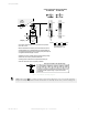
The actuating system must travel the required distance to operate the positive opening normally closed contacts, but not
exceed the maximum travel listed on the switching diagrams. The installation must account for any mechanical
inaccuracies, tolerance issues, wear, misalignment, etc. in the actuator (cam) and the actuating system of the switch by
allowing sufficient post-travel after the positive opening point.
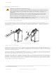
When used in a safety application, the actuating system must be operated by direct mechanical action (positive mode) of
the actuator (cam) and the guard that engage the direct positive opening of the normally closed safety contacts. Non-
direct mechanical action (negative mode) that relies on spring force should only be used in conjunction with a Type 1 or
Type 2 (key/tongue actuated) interlocking switch mounted in the direct action positive mode as a redundant,
complementary monitoring channel (see Figure 6 on page 10).
Actuators (cams) must be designed and installed to:
• Ensure that the limit switch contacts are operated long enough to ensure that a proper signal is transmitted to
operate connected devices or safety modules and controllers
• Ensure the actuator is not operated beyond its overtravel limits
• Ensure that the actuator does not receive severe impact from fast moving cams
• Ensure the actuator does not snap back into to position by an abrupt release
• Not use additional or modified actuators
Do not use the switch, actuating system, or the actuator (cam) as a mechanical end of travel stop. If you change the
position of the actuator, ensure the correct reassembly for proper operation.
Safety Limit Switches
4 www.bannerengineering.com - Tel: +1-763-544-3164 P/N 182191 Rev. A