
Cut Sheet


CAUTION: End-of-Travel Stop
Do not use the safety switch as a mechanical or end-of-travel stop.
The movement or rotation of the guard must be limited such that damage to the safety switch or the
actuator cannot occur. Catastrophic damage can cause the safety switch to fail in an unsafe
manner (that is, loss of the switching action).
WARNING: Safety Distances and Safe Openings
It must not be possible for personnel to reach any hazard through an opened guard or by reaching
over, under, around, or through any opening in the guard before the hazardous situation has ceased.
See ANSI B11.19 or ISO 14119, ISO 14120 and ISO 13857 for information on determining safety
distances and safe opening sizes for your guarding device.
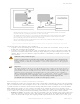
Pass-through hazards and Perimeter Guarding
A pass-through hazard is associated with applications where personnel may pass through a safeguard (which issues a stop
command to remove the hazard), and then continues into the guarded area, such as in perimeter guarding. Subsequently,
their presence is no longer detected, and the related danger becomes the unexpected start or restart of the machine while
personnel are within the guarded area.
Eliminate or reduce pass-through hazards whenever possible—see ANSI B11.19 and ANSI B11.20 or ISO 11161. One
method to mitigate the risk is to ensure that once tripped, either the safeguarding device, the safety related part of the
control system, or the guarded machine's MSCs/MPCEs will latch in an OFF condition. The latch must require a deliberate
manual action to reset that is separate from the normal means of machine cycle initiation.
This method relies upon the location of the reset switch as well as safe work practices and procedures to prevent an
unexpected start or restart of the guarded machine. All reset switches must be:
• Outside the guarded area
• Located to allow the switch operator a full, unobstructed view of the entire guarded area while the reset is
performed
• Out of reach from within the guarded area
• Protected against unauthorized or inadvertent operation (such as through the use of rings or guards)
If any areas within the guarded area are not visible from the reset switch, additional safeguarding must be provided.
WARNING: Pass-Through Hazards and Perimeter Guarding
Lockout/Tagout procedures per ANSI Z244.1 may be required, or additional safeguarding, as described
by ANSI B11.19 safety requirements or other appropriate standards, must be used if a passthrough
hazard cannot be eliminated or reduced to an acceptable level of risk. Failure to observe this warning
may result in serious bodily injury or death.
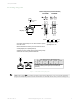
Mechanical Installation
Important: Install a safety switch in a manner which discourages tampering or defeat. Mount switches
to prevent bypassing of the switching function at the terminal chamber or Quick Disconnect (QD). A
switch and its actuator must never be used as a mechanical stop. Overtravel may cause damage to
switch.
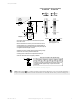
All mounting hardware is supplied by the user. Fasteners must be of sufficient strength to guard against breakage. Use of
permanent fasteners or locking hardware is recommended to prevent the loosening or displacement of the actuator and
the switch body. The mounting holes in the switch body accept M5 screws.
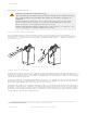
Safety limit switches and their actuators (cams, dogs, etc.) must be mounted such that the position cannot be changed
after installation/adjustment. Mount the switch securely on a solid, stationary surface that can accommodate the forces of
actuator movement. The loosening of mounting hardware must be prevented (for example, lock washers, thread-locking
compound). The use of slots should only be used for initial positioning. Pins, dowels, and splines can be used to prevent
movement of the switch and the actuator (cam).
The safety limit switch must be installed to prevent false or unintended actuation and intentional defeat.
Safety limit switches should be located in such a manner that allows access for functional checks, maintenance, and
service or replacement. The installation should provide suitable clearances, be readily accessible, and allow access to the
actuator system (for example, roller lever) and switch body covers.
Safety Limit Switches
P/N 182191 Rev. A www.bannerengineering.com - Tel: +1-763-544-3164 3