
Cut Sheet
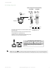

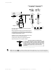


Normally closed safety contacts (11/12 or 21/22) are monitored by the safety module when both switches are mounted in
the positive mode (that is, opening the guard actuates S1 and S2; circuit on left).
One normally closed safety contact (11/12 or 21/22) from the switch mounted in the positive mode (S1) and one normally
open contact (23/24 or 33/34) from the switch mounted in the negative mode (S2) are monitored by the safety module
(that is, opening the guard actuates S1 and releases S2; circuit on right).
Refer to the installation instructions provided with the safety module or safety controller for information regarding the
interface to the machine stop control elements.
Figure 6. Connect two redundant safety switches per interlock guard to an appropriate 2-channel input safety module
Two functions of the safety module or safety controller are:
1. To provide a means of monitoring the contacts of both safety switches for contact failure, and to prevent the
machine from restarting if either switch fails.
2. To provide a reset routine after closing the guard and returning the safety contacts to their closed position. This
prevents the controlled machinery from restarting by simply closing the guard (reinserting the key/actuator, for
example). This necessary reset function is required by ANSI B11.0, ANSI/NFPA 79, and IEC 60204-1 machine
safety standards.
WARNING: Safety Circuit Integrity
A risk assessment must be performed to determine the appropriate safety circuit integrity
level or category to ensure the expected risk reduction is achieved and all relevant regulations and
standards are met (see ANSI B11.0 and ANSI B11.19, ISO 12100 and ISO13849-1 or the appropriate
standards).
Important:
The design, installation, and the means of interfacing of the safety switches greatly impact the level of
safety circuit integrity. It is recommended that two individual safety switches be used to monitor each
guard and that at least one normally-closed safety contact and an additional contact, depending on the
application, must be connected in a dual channel method to a safety module or safety controller to
achieve control reliability (ANSI B11.19) or Category 3 or 4 (ISO 13849-1, EN 954-1). This is required
to provide monitoring for safety switch failure, and to provide the necessary reset routine, as required
by NFPA 79 and IEC 60204-1. Use of only one safety switch per interlock guard is not
recommended in situations that can result in serious injury or death.
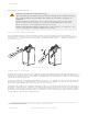
Monitoring Series-Connected Safety Switches
When monitoring the position of several guards with a single safety module or controller, the contacts of the corresponding
pole of each switch must be connected together in series. Never connect the contacts of multiple switches in parallel. Such
a parallel connection can defeat the switch contact monitoring ability of the module and could create an unsafe condition.
When multiple safety switches are series connected, the failure of one switch in the system may be masked or not be
detected at all. The following two scenarios assume two positive-opening safety switches on each guard, both connected in
series to switches of a second guard (dual channel hookup) and monitored by a safety module or safety controller:
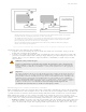
• Masking of a failure—If a guard is opened but one switch fails to open, the redundant safety switch on that guard
opens and a protective (safety) stop occurs. If the faulty guard is then closed, the module/controller will not reset
because one channel did not open, thus complying with the required fault detection. However, if a second "good"
Safety Limit Switches
10 www.bannerengineering.com - Tel: +1-763-544-3164 P/N 182191 Rev. A