
Quick Start Guide

Quick Start Guide
Self-Contained, AC-Operated Sensors
For additional technical information about this product, including complete instructions, dimensions, accessories, and
specifications, see http://www.bannerengineering.com and search 121519.
WARNING: Not To Be Used for Personnel Protection
Never use this device as a sensing device for personnel protection. Doing
so could lead to serious injury or death. This device does not include the self-
checking redundant circuitry necessary to allow its use in personnel safety
applications. A sensor failure or malfunction can cause either an energized or de-
energized sensor output condition.
Models
Sensing Mode
Model
1
Output Range LED
OPPOSED
S303E —
60 m (196.8 ft) Infrared, 950 nmS30AW3R LO
S30RW3R DO
P
POLAR RETRO
S30AW3LP LO
6 m (19.7 ft) Visible red, 680 nm
S30RW3LP DO
FIXED-FIELD
S30AW3FF200 LO
200 mm (7.9 in) cutoff
Infrared, 880 nm
S30RW3FF200 DO
S30AW3FF400 LO
400 mm (15.7 in) cutoff
S30RW3FF400 DO
S30AW3FF600 LO
600 mm (23.6 in) cutoff
S30RW3FF600 DO
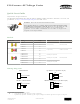
Wiring Diagrams
Cabled Emitters
bn
bu
20-250V ac
QD Emitters (4-pin Micro-Style)
20-250V ac
No connection
rd/wh
rd/bk
rd
gn
All Other Cabled Models
bn
bu
bk
20-250V ac
Load
All Other QD Models (4-pin Micro-Style)
20-250V ac
No Connection
Load
rd/wh
rd
rd/bk
gn
1
Standard 2 m (6.5 ft) cable models are listed.
• 9 m (30 ft) cable: add suffix "W/30" (for example, S303E W/30).
• 4-pin Micro-style QD models: add suffix "Q1" (for example, S303EQ1). A model with a QD connector requires a mating cable.
S30 Sensors AC-Voltage Series
Original Document
116158 Rev. A
30 December 2015
116158