
Cut Sheet
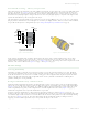
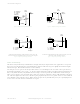
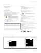
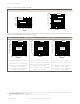
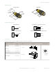
Table Of Contents

Table 2: Polarized Retro Mode Sensors
2
Beam Pattern Excess Gain
7.5 m
(25')
6.0 m
(20')
4.5 m
(15')
3.0 m
(10')
1.5 m
(5')
0
0
50 mm
100 mm
150 mm
50 mm
100 mm
150 mm
0
2"
4"
6"
2"
4"
6"
DISTANCE
S30 Series
Polarized Retro
with BRT-3 Reflector
1
10
100
0.1 m
(0.33')
1 m
(3.3')
10 m
(33')
0.01 m
(0.033')
1000
E
X
C
E
S
S
G
A
I
N
DISTANCE
S30 Series
Polarized Retro
with BRT-3 Reflector
Table 3: Fixed-Field Mode Sensors Excess Gain
3
Fixed-Field — 200 mm Fixed-Field — 400 mm Fixed-Field — 600 mm
1
10
100
10 mm
(0.4")
100 mm
(4")
1000 mm
(40")
1 mm
(0.04")
E
X
C
E
S
S
G
A
I
N
DISTANCE
1000
S30 Series
Fixed-field mode
with 200 mm far
limit cutoff
Ø 16 mm spot size at 35 mm focus
Ø 20 mm spot size at 200 mm cutoff
Using 18% gray test card: cutoff distance
will be 95% of value shown.
Using 6% black test card: cutoff distance
will be 90% of value shown.
1
10
100
10 mm
(0.4")
100 mm
4")
1000 mm
40")
1 mm
(0.04")
E
X
C
E
S
S
G
A
I
N
DISTANCE
1000
S30 Series
Fixed-field mode
with 400 mm far
limit cutoff
Ø 17 mm spot size at 35 mm focus
Ø 25 mm spot size at 400 mm cutoff
Using 18% gray test card: cutoff distance
will be 90% of value shown.
Using 6% black test card: cutoff distance
will be 85% of value shown.
1
10
100
10 mm
(0.4")
100 mm
(4")
1000 mm
(40")
1 mm
(0.04")
E
X
C
E
S
S
G
A
I
N
DISTANCE
1000
S30 Series
Fixed-field mode
with 600 mm far
limit cutoff
Ø 17 mm spot size at 35 mm focus
Ø 30 mm spot size at 600 mm cutoff
Using 18% gray test card: cutoff distance
will be 85% of value shown.
Using 6% black test card: cutoff distance
will be 75% of value shown.
2
Performance based on use of a model BRT-3 retroreflector (3-inch diameter). Actual sensing range may be more or less than specified, depending on the
efficiency and reflective area of the retroreflector used.
3
Performance based on use of a 90% reflectance white test card. Focus and spot sizes are typical.
S30 Sensors AC-Voltage Series
P/N 121519 Rev. A www.bannerengineering.com - Tel: +1-763-544-3164 5