
Cut Sheet
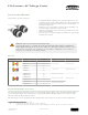
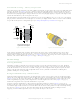
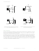
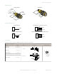
Table Of Contents

Specifications
Supply Voltage and Current
20 av V to 250 V ac (50 Hz to 60 Hz)
Average current: 20 mA
Peak current:
200 mA at 20 V ac
500 mA at 120 V ac
750 mA at 250 V ac
Supply Protection Circuitry
Protected against transient voltages
Output Configuration
SPST solid-state ac switch; three-wire hookup; light operate or dark
operate, depending on model
Light Operate: Output conducts when sensor sees its own (or the
emitter’s) modulated light
Dark Operate: Output conducts when the sensor sees dark
Required Overcurrent Protection
WARNING: Electrical connections must be
made by qualified personnel in accordance
with local and national electrical codes and
regulations.
Overcurrent protection is required to be provided by end product
application per the supplied table.
Overcurrent protection may be provided with external fusing or via
Current Limiting, Class 2 Power Supply.
Supply wiring leads < 24 AWG shall not be spliced.
For additional product support, go to http://
www.bannerengineering.com.
Supply Wiring (AWG)
Required Overcurrent Protection (Amps)
20 5.0
22 3.0
24 2.0
26 1.0
28 0.8
30 0.5
Output Rating
300 mA maximum (continuous)
Fixed-Field models: derate 5 mA/°C above +50° C (+122° F)
Inrush capability: 1 amp for 20 ms, non-repetitive
OFF-state leakage current: < 100 mA
ON-state saturation voltage: 3 V at 300 mA ac; 2 V at 15 mA ac
Output Protection Circuitry
Protected against false pulse on power-up
Output Response
Time Opposed mode: 16 ms ON, 8 ms OFF
Other models: 16 ms ON and OFF
NOTE: 100 ms delay on power-up; outputs
do not conduct during this time.
Repeatability
Opposed mode: 2 ms
Other models: 4 ms
Repeatability and response are independent of signal strength
Indicators
Two LEDs (Green and Yellow)
Green ON steady: power to sensor is ON
Yellow ON steady: sensor sees light
Yellow flashing: excess gain marginal (1 to 1.5 times) in light
condition
Construction
PBT polyester housing; polycarbonate (opposed-mode) or acrylic lens
Environmental Rating
Leakproof design rated NEMA 6P, DIN 40050 (IEC IP69K)
Connections
2 m (6.5 ft) attached cable, or 4-pin Micro-style quick-disconnect fitting
Operating Conditions
Temperature: −40 °C to +70 °C (−40 °F to +158 °F)
Humidity: 90% at +50 °C maximum relative humidity (non-
condensing)
Vibration and Mechanical Shock
All models meet Mil. Std. 202F requirements. Method 201A (Vibration;
frequency 10 Hz to 60 Hz, max., double amplitude 0.06 inch
acceleration 10G). Method 213B conditions H&I. (Shock: 75G with unit
operating; 100G for non-operation)
Certifications
Performance Curves
Table 1: Opposed Mode Sensors
Beam Pattern
Excess Gain
75 m
(250')
60 m
(200')
45 m
(150')
30 m
(100')
15 m
(50')
0
0
250 mm
500 mm
750 mm
250 mm
500 mm
750 mm
0
10"
20"
30"
10"
20"
30"
DISTANCE
S30 Series
Opposed Mode
1
10
100
1 m
(3.3')
10 m
(33')
100 m
(330')
0.1 m
(0.33')
1000
E
X
C
E
S
S
G
A
I
N
DISTANCE
S30 Series
Opposed Mode
S30 Sensors AC-Voltage Series
4 www.bannerengineering.com - Tel: +1-763-544-3164 P/N 121519 Rev. A