
Cut Sheet
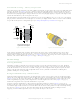
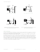
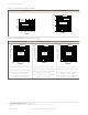
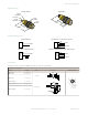
Table Of Contents

Fixed-Field Sensing – Theory of Operation
The S30FF compares the reflections of its emitted light beam (E) from an object back to the sensor’s two differently aimed
detectors, R1 and R2. See Figure 1 on page 2. If the near detector's (R1) light signal is stronger than the far detector's
(R2) light signal (see object A in the Figure below, closer than the cutoff distance), the sensor responds to the object. If
the far detector's (R2) light signal is stronger than the near detector's (R1) light signal (see object B in the Figure below,
beyond the cutoff distance), the sensor ignores the object.
The cutoff distance for model S30FF sensors is fixed at 200, 400, or 600 millimeters (7.9 in, 16.7 in, or 23.6 in). Objects
lying beyond the cutoff distance are usually ignored, even if they are highly reflective. However, under certain conditions,
it is possible to falsely detect a background object (see Background Reflectivity and Placement on page 2).
R1
R2
Lenses
Object
A
Object B
or
Background
Sensing
Range
Cutoff
Distance
E
Receiver
Elements
Near
Detector
Far
Detector
Emitter
Object is sensed if amount of light at R1
is greater than the amount of light at R2
Figure 1. Fixed-Field Concept Figure 2. Fixed-Field Sensing Axis
In the drawings and information provided in this document, the letters E, R1, and R2 identify how the sensor’s three
optical elements (Emitter “E”, Near Detector “R1”, and Far Detector “R2”) line up across the face of the sensor. The
location of these elements defines the sensing axis, see Figure 2 on page 2. The sensing axis becomes important in certain
situations, such as those illustrated in Figure 5 on page 3 and Figure 6 on page 3.
Device Setup
Sensing Reliability
For highest sensitivity, position the target object for sensing at or near the point of maximum excess gain. Maximum
excess gain for all models occurs at a lens-to-object distance of about 40 mm (1.5 in). Sensing at or near this distance
makes the maximum use of each sensor’s available sensing power. The background must be placed beyond the cutoff
distance. Note that the reflectivity of the background surface also may affect the cutoff distance. Following these
guidelines will improve sensing reliability.
Background Reflectivity and Placement
Avoid mirror-like backgrounds that produce specular reflections. A false sensor response occurs if a background surface
reflects the sensor’s light more to the near detector (R1) than to the far detector (R2). The result is a false ON condition
(Figure 3 on page 3). To correct this problem, use a diffusely reflective (matte) background, or angle either the sensor
or the background (in any plane) so the background does not reflect light back to the sensor (Figure 4 on page 3).
Position the background as far beyond the cutoff distance as possible.
An object beyond the cutoff distance, either stationary (and when positioned as shown in Figure 5 on page 3), or
moving past the face of the sensor in a direction perpendicular to the sensing axis, may cause unwanted triggering of the
sensor if more light is reflected to the near detector than to the far detector. The problem is easily remedied by rotating
the sensor 90° (Figure 6 on page 3). The object then reflects the R1 and R2 fields equally, resulting in no false
triggering. A better solution, if possible, may be to reposition the object or the sensor.
S30 Sensors AC-Voltage Series
2 www.bannerengineering.com - Tel: +1-763-544-3164 P/N 121519 Rev. A