
User's Manual


Page 2 of 5
each of length T
slot
. During each time slot, a given radio could spend part of its time
transmitting (T
on
), receiving, or idle to conserve energy. To be in compliance with the
rules for dwell time as tested, the radio transmitter must be on less than 50 % of the time.
Power Control
Users must ensure that they are maintain a conducted output power of 26 dBm or
less. Contact the factory for details on adjusting RF power levels.
Operation
Operational details for the radio appear in the PowerPoint document
“RM912HP_06_user_manual”. Refer to that document for connection diagrams, pad
layouts, and other implementation details. The other primary reference is the data sheet
for the transceiver IC. Please contact Banner Engineering for copies of that reference.
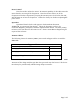
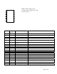
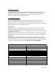
Antenna Choices
The following classes of antennas (Table 1) were tested and approved for use with
the RM912HP.
Approved antennas
Antenna style Gain
High gain helical loaded omnidirectional monopole
<= 5 dBi
High gain omnidirectional dipole
<= 8 dBi
High gain Yagi directional
<= 6 dBi)
Table 1
Antennas of like design with less gain than the type tested may also be used. The device
is always professionally installed and uses unique connectors.