
User's Manual


Page 2 of 5
Power Control
Users that wish to utilize the entire 1 W transmit capability of this radio must also
ensure that they are using all 50 frequencies. Users that do not wish to use all 50
frequencies must then compensate by keeping the transmit power level below 250 mW,
and still must use at least 25 frequencies. Contact the factory for details on adjusting RF
power levels.
Operation
Operational details for the radio appear in the PowerPoint document
“RM912HP_01_operational_description”. This is the document to refer to for
connection diagrams, pad layouts, and other implementation details. The other primary
reference is the data sheet for the transceiver IC. Please contact Banner Engineering for
copies of that reference.
Antenna Choices
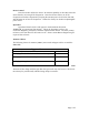
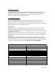
The following classes of antennas (Table 1) were tested and approved for use with the
RM912HP.
Approved antennas
Antenna style Gain
High gain helical loaded omnidirectional monopole
<= 5 dBi
High gain omnidirectional dipole
<= 8 dBi
High gain Yagi directional
<= 6 dBi)
Table 1
Antennas of like design with less gain than the type tested may also be used. The device
must always be professionally installed using unique connectors.