
User's Manual

Overview
The Banner RM7023 device is a frequency hopping spread spectrum transceiver operating in the
902 – 928 MHz band. When mounted to a carrier board containing a microcontroller and voltage
regulator, the pair is known as the DX180.
The DX180 employs a time-slotted architecture to support point to point, point to multipoint,
peer to peer and TDMA network topologies. Some operational parameters (number of hop table
frequencies, power levels, TDMA “slot times”) are configurable at the system level to provide
maximum flexibility for particular applications and network topologies, but for a given
architecture the parameters will not change in the field. This document will discuss fixed and
configurable parameters and their relation to meeting the FCC specifications. Such parameters
include the frequency plan, the time sharing architecture, power control, and approved antennas.
Also discussed will be the partitioning of radio functions as pertaining to the limited Modular
Approval for the device.
Frequency Plan
The radio is capable of transmitting or receiving on any of 64 equally spaced, non-overlapping
channels available in the 902-928 MHz band. (902.4, 902.8…927.6 MHz) From this set of 64, a
subset of M (M <= 64) unique frequencies will be chosen to populate the hop table. The subset
of M frequencies will be configured at the factory and will not be field adjustable. The radio
hops through each successive entry in the hop table in pseudorandom order and then repeats,
never truncating the list and starting over. The receiver is a direct conversion type (zero-IF)
meaning there are no additional intermediate frequency oscillators.
TDMA Plan
The radio is intended for operation in deterministic and ad-hoc networks. The communications
channel is shared in these networks using a time domain multiple access protocol. The
underlying structure to this protocol is a frame made up of N time slots, each of length T
slot
.
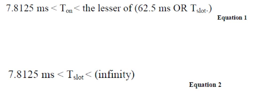
During each time slot, a given radio could spend part of its time transmitting (T
on
), receiving, or
idle to conserve energy. For this system, the time spent transmitting per time slot, T
on
, is limited
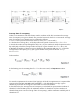
in software to be between 7.8125 ms and 62.5 ms. Obviously, if the Time Slot Duration T
slot
is
less than 62.5 ms, then that would be the maximum on-time per slot (by definition a transmission
can not occupy more than 100% of T
slot
.) The relationship between T
slot
, T
on
and transmit and
receiving is illustrated graphically in Figure 1, below.
The actual duration of the slot (T
slot
) is not explicitly constrained, but is governed by practical
limitations. At minimum, T
slot
must be long enough for the radio circuitry to stabilize on a given
channel. At maximum, Tslot must be short enough to allow networks to form and communicate
expediently. From
Equation 1
, it can be seen that T
slot
in this system will always be greater than
7.8125 ms.