
User's Manual


SureCross™ DX80 Quick Start Guide
P/N 128185 Rev B 7
Banner Engineering Corp. • Minneapolis, MN U.S.A.
www.bannerengineering.com • Tel: 763.544.3164
Quick Start: STEP 3
> Apply Power, Node
Quick Start: STEP 2
> Apply Power, Gateway
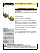
To apply power to the Gateway, connect the 10-30V dc cable as shown.
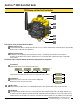
To apply power to the Node, connect the 10-30V dc cable or DX81 Battery Module as shown.
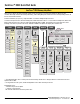
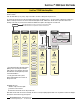
Apply power...
This reading occurs only when power is
applied to the Gateway.
The LCD display
shows the current I/O
status of the Gateway.
The Gateway starts in *RUN mode.
Displays current Network ID (NID)
Device is ...
... Gateway (Device Address = 0)
Indicates the current status of the I/O.
The display cycles through each I/O
point of the device, then returns to
*RUN.
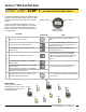
Apply power...
This reading occurs only when power
is applied to the Node.
The LCD display
shows the current I/O
status of the Node.
The Node starts in *RUN mode.
Displays current Network ID (NID)
Device is ...
... Node 1 (Node Address = 1)
Indicates the current status of the I/O.
The display cycles through each I/O
point of the device, then returns to
*RUN.
Notes
Display/Status
User Action
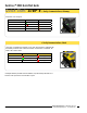
Brown 1 10-30V dc Input
Blue 3 dc common
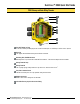
Gateway Pinout Diagram
On the Gateway, the other pins are used for
RS485 communications
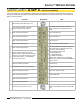
Brown 1 10-30V dc Input
Blue 3 dc common
Line Powered Node Pinout Diagram
Note: Terminal block GND = dc common