
User's Manual


SureCross™ DX80 Quick Start Guide
2 P/N 128185 Rev B
Banner Engineering Corp. • Minneapolis, MN U.S.A.
www.bannerengineering.com • Tel: 763.544.3164
1
2
3
4
5 6
7
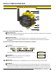
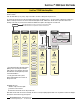
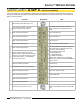
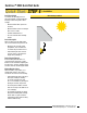
Rotary Switch 1 (left)
Sets the Network ID (NID) to a hexidecimal value from 0 to F, for a total of 16 Network IDs. A Gateway and its corresponding
Nodes must be assigned the same Network ID.
Rotary Switch 2 (right)
On Gateway: Sets the Gateway’s LCD viewing device address. The Gateway is predefined as Device Address 0.
On Node: Sets the Node’s Device Address (hexidecimal 1 to F). Each Node within a network must have a unique Node
Device Address.
Push Button 1
Single-click to advance across all top-level DX80 menus.
Single-click to move down interactive menus, once a top-level menu is chosen.
Push Button 2
Double-click to select a menu and to enter manual scrolling mode.
Double-click to move up one level at a time.
LED 1 and 2
Provide real-time feedback to the user regarding RF link status, serial communications activity, and the error state.
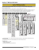
LCD Display
Six-character display provides run mode user information and shows enabled I/O point status. This display allows the user
to conduct a Site Survey (RSSI) and modify other DX80 configuration parameters without the use of a PC or other external
software interfaces. On the Node, after 15 minutes of inactivity, the LCD goes blank. Press any button to refresh the display.
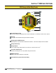
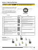
Rotary Switches: Used to set Network ID & Device Address
Push Buttons: Used to navigate the Gateway and Node menus and program device configurations
Single-click
Button 1
Single-click
Button 1
Double-click
Button 2
Double-click
Button 2
etc.
Single-click
Button 1
etc.
DX80 Gateway and Node Front Panel Interface
1
2
3
4
5
6
7