
User's Guide


SureCross™ 1 Watt Data Radio
4 P/N 132031
Banner Engineering Corp. • Minneapolis, MN U.S.A.
www.bannerengineering.com • Tel: 763.544.3164
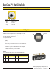
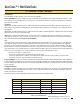
Hookup Diagrams
Color No. Description
Brown 1 10 to 30V dc Input
White 2 RS485 / D1 / B /+
Blue 3 dc common
Black 4 RS485 / D0 / A / -
Gray 5 Comms Gnd
5-pin M12 Euro Hookup
Note: Terminal block GND = dc common
Configuration
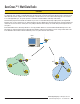
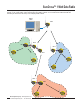
Network and Device ID
Since the data stream appearing on the serial input of one radio
within the network is reproduced on the serial outputs of all other
radios in the same network, the only configuration necessary is to
set up the network ID and device ID.
To setup the data radio:
Set each radio in the same network to the same network ID
(NID).
Set the device ID of one radio in each NID network to zero.
This radio acts as the time keeper for the radio network and
can be any radio in the network.
Set the device IDs for the other radios within the same
network to any device number other than zero. Except for
the one radio set to device ID zero, the other device ID
settings are ignored by the radio network.
1.
2.
3.
Network ID
Device ID
Switches
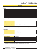
Use the switches on the board to set the baud rate and parity.
Baud Rate Switches Parity Switches
1 2 3 4
Off Off 19200 (default)* Off Off None (default)*
On Off 9600 On Off Odd
Off On 38400 Off On Even
On On 19200 On On None
* Default position shown