
Cut Sheet

Overview
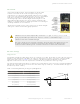
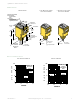
Status indicator LEDs for Power, Signal and Output are clearly visible
beneath a raised dome in the sensor’s transparent o-ring-sealed
polycarbonate cover. The Power indicator lights whenever power is applied
to the sensor. The Signal LED lights whenever the sensor sees its modulated
light source, and pulses at a rate proportional to the strength of the
received light signal; this is the AID
™
Alignment Indicating Device. The
Output indicator lights whenever the sensor’s output is conducting. This
indicator is especially useful when a timing logic module is used and Signal
and Output conditions are not concurrent.
Also located beneath the sensor’s o-ring-sealed cover are controls for light/
dark operate selection and Sensitivity (gain) adjustment.
Sensitivity
Adjustment
Output Status
Indicator
Power ON
Indicator
Light/Dark
Operate Switch
Optional LED
Signal Strength
Display
Optional Timing
Adjustments
Signal Indicator
CAUTION: Never stare directly into the sensor lens. Laser light can damage your eyes. Avoid
placing any mirror-like object in the beam. Never use a mirror as a retroreflective target.
CAUTION: Do Not Disassemble for Repair
This device contains no user-serviceable components. Do not attempt to disassemble for repair. Use
of controls or adjustments or performance of procedures other than those specified herein may
result in hazardous radiation exposure. A defective unit must be returned to the manufacturer.
Device Setup
Alignment
Conventional retroreflective photoelectric sensors are extremely easy to align. Beam angles are wide, and retro targets are
forgiving to angle of incidence of the light beam. The beam of the Q45 laser sensor is very narrow, compared with the
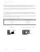
beam of most retro sensors. As Table 1 on page 2 indicates, the effect of angular misalignment can be dramatic.
Alignment is critical because the beam may miss the retroreflective target unless the retro target is large.
For example, with one BRT-2x2 mounted at a distance of 6 m (20 ft) from the sensor, one degree of angular misalignment
will cause the center of the laser beam to miss the center of the target by 4 inches (i.e., the beam will miss the edge of
the reflector by almost 3 inches).
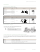
Table 1: Beam Displacement per Degree of Misalignment
Sensor-to-Target Distance (X)
Beam Displacement (Y) for 1
1.5 m (5 feet) 25 mm (1 inches)
3 m (10 feet) 50 mm (2 inches)
3 m (10 feet) 100 mm (4 inches)
15 m (50 feet) 250 mm (10 inches)
30 m (100 feet) 500 mm (20 inches)
45 m (150 feet) 750 mm (30 inches)
60 m (200 feet) 1000 mm (40 inches)
Sensing Distance = X
Ø = Misalignment Angle
Y = X(tan Ø)
Y
C
L
Q45BB6LL Laser Diode Retroreflective Sensors
2 www.bannerengineering.com - Tel: +1-763-544-3164 P/N 38244 Rev. C