
Cut Sheet
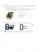
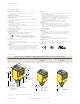
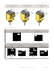
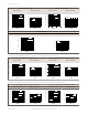

Table Of Contents

Overview
Status indicator LEDs for power, signal, and output are clearly visible beneath a raised dome in the sensor’s transparent o-
ring-sealed polycarbonate cover. Also located beneath the sensor’s o-ring-sealed cover are controls for light/dark operate
selection and the sensitivity adjustment.
• The power indicator (green) lights when power is applied to the sensor.
• The signal indicator (red) lights when the sensor sees its modulated light source and pulses at a rate proportional
to the strength of the received light signal; this is the AID
™
Alignment Indicating Device
2
.
• The output indicator (amber) lights when the sensor’s output is conducting. This indicator is especially useful when
a timing logic module is used and signal and output conditions are not concurrent.
1
3
4
5
6
2
1. Sensitivity adjustment
2. LEDs
• Green LED: Power on indicator
• Red LED: Signal indicator
• Amber LED: Output status indicator
3. Optional LED signal strength display
4. Optional timing adjustment
5. Optional timing adjustment
6. Light/dark operate switch
Wiring Diagrams
Q45BB6 Sensors with Attached Cable
10-30V dc
–
+
1
3
2
4
Load
Load
Q456E Emitters with Attached Cable
10-30V dc
–
+
1
3
Key:
1=Brown
2=White
3=Blue
4=Black
NOTE: Wiring for quick disconnect (QD) models (model suffix Q and Q5) are functionally identical.
2
US patent no. 4356393
Q45BB6 Series Sensors
4 www.bannerengineering.com - Tel: +1-763-544-3164 P/N 36578 Rev. E