
User's Manual

1
2
5
6
3
4
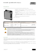
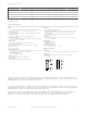
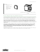
Figure 1. R-GAGE features
1. Output LEDs: Yellow (output 1 energized); Red
(configuration)
2. Output LEDs: Yellow (output 2 energized); Red
(configuration)
3. Power LED: Green (power ON)
4. Signal Strength LED: Red (flashes in proportion to
the signal strength)
5. DIP switch row A
6. DIP switch row B
Access the DIP switches behind the threaded cap on the
sensor side
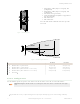
D
X Y
A B
Zone 1 Zone 2
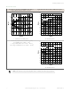
Figure 2. R-GAGE setpoint distances
CN Model
US Model
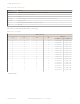
X Minimum Zone 1 setpoint distance 2 m (6.6 ft) 3.5 m (11.5 ft)
Y Maximum Zone 1 setpoint distance 30 m (98.4 ft) 30 m (98.4 ft)
A Minimum Zone 2 (offset from Zone 1: 2 m to 25 m) 4 m (13.1 ft) 5.5 m (18.0 ft)
B Maximum Zone 2 (offset from Zone 1: 2 m to 25 m) 55 m (180.4 ft) 55 m (180.4 ft)
D Dead Zone
1
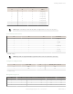
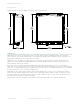
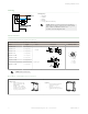
Sensor Configuration
Use the included spanner to open the screw-off cover on the side of the sensor and access the DIP switches.
Important: Tighten the DIP switch cover a full quarter turn after contact to maintain the watertight
seal.
1
Typical dead zone: 0.4 m (1.3 ft) for moving and 1.0 m (3.3 ft) for stationary targets, but varies with target reflectivity.
R-GAGE
™
Q240RA-AF2 Sensor
2 www.bannerengineering.com - Tel: +1-763-544-3164 P/N 184564 Rev. A