
Cut Sheet

Class 2 Lasers
Class 2 lasers are lasers that emit visible radiaon in the wavelength range from 400 nm to
700 nm, where eye protecon is normally aorded by aversion responses, including the blink
reex. This reacon may be expected to provide adequate protecon under reasonably
foreseeable condions of operaon, including the use of opcal instruments for intrabeam
viewing.
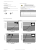
Figure 3. FDA (CDRH) warning label (Class
2)
Class 2 Laser Safety Notes
Low-power lasers are, by denion, incapable of causing eye injury within the duraon of a
blink (aversion response) of 0.25 seconds. They also must emit only visible wavelengths (400
to 700 nm). Therefore, an ocular hazard may exist only if individuals overcome their natural
aversion to bright light and stare directly into the laser beam.
Sensor Installaon
Note: Handle the sensor with care during
installaon and operaon. Sensor windows soiled by ngerprints, dust,
water, oil, etc. may create stray light that may degrade the peak performance of the sensor. Blow the window clear
using ltered, compressed air, then clean as necessary using 70% isopropyl alcohol and coon swabs or water and a
so cloth.
Mount the Sensor
1. If a bracket is needed, mount the sensor onto the bracket.
2. Mount the sensor (or the sensor and the bracket) to the machine or equipment at the desired locaon. Do not ghten the
mounng screws at this me.
3. Check the sensor alignment.
4. Tighten the mounng screws to secure the sensor (or the sensor and the bracket) in the aligned posion.
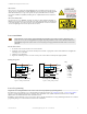
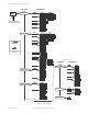
Wiring Diagrams
shield
+
12-30V dc
D_Out
A_Out
Input
–
Load
* User-configurable PNP/NPN setting
4-20 mA
3
1
2
4
5
NPN
or
PNP
Figure 4. Analog Current Model
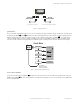
shield
+
12-30V dc
D_Out
A_Out
Input
–
Load
* User-configurable PNP/NPN setting
3
1
2
4
5
NPN
or
PNP
0-10V
Figure 5. Analog Voltage Model
Key
2
3
4
1
5
1 = Brown
2 = White
3 = Blue
4 = Black
5 = Gray
Sensor Programming
Program the sensor using the buons on the sensor or the remote input (limited programming opons).
From Run mode, use the buons to access the Quick Menu and the Sensor Menu. See Quick Menu on page 4, Sensor Menu (MENU)
on page 4, and the instrucon manual (p/n 194135) for more informaon on the opons available from each menu. For TEACH
opons, follow the TEACH instrucons in the instrucon manual.
In
addion to programming the sensor, use the remote input to disable the buons for security, prevenng unauthorized or accidental
programming changes. See the instrucon manual for more informaon.
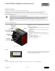
L-GAGE
®
LTF Time of Flight Laser Distance Sensor
P/N 194136 Rev. D www.bannerengineering.com - Tel: +1-763-544-3164 3