
Cut Sheet

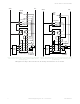
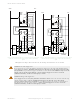
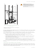
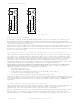
Table Of Contents

CAUTION: Abuse of Module After Failure
If an internal fault has occurred and the Module will not reset, do not tap, strike, or otherwise
attempt to correct the fault by a physical impact to the housing. An internal relay may have
failed in such a manner that its replacement is required.
If the Module is not immediately replaced or repaired, multiple simultaneous failures may
accumulate such that the safety function can not be guaranteed.
Specifications
Power
General
Input Voltage and Current
24 V dc, +/-15% no polarity, 10% maximum ripple; 50 mA per input
channel (approximately 2.4 W)
Supply Protection Circuitry
Protected against transient voltages
Overvoltage Category
Output relay contact voltage of 1 V to 150 V ac/dc: Category III
Output relay contact voltage of 151 V to 250 V ac/dc: Category II
(Category III, if appropriate overvoltage reduction is provided)
Vibration Resistance
10 HZ to 55 Hz @ 0.35 mm displacement per IEC 60068-2-6
Pollution Degree
2
Status Indicators
2 green LED indicators: K1 energized, K2 energized
Construction
Polycarbonate housing rated NEMA 1, IEC IP20
Mounting
Mounts to standard 35 mm DIN-rail track. Interface Module must be
installed inside an enclosure rated NEMA 3 (IEC IP54), or better.
Application Notes
There are no adjustments and no user-serviceable parts. See Repairs
for information regarding repair service.
Output Configuration
Outputs
IM-T-9A: 3 normally open output channels
IM-T-11A: 2 normally open output channels and 1 normally closed
auxiliary output channel
Each normally open output channel is a series connection of contacts
from two forced-guided (mechanically linked) relays, K1-K2. The
normally closed contact 31-32 is a parallel connection of contacts from
K1-K2.
Contacts
AgNi, 5 μm gold-plated
Low Current Rating
The 5 μm gold-plated contacts allow the switching of low current/low
voltage. In these lowpower applications, multiple contacts can also be
switched in series (e.g., “dry switching”). To preserve the gold plating
on the contacts, do not exceed the following max. values at any time:
Min. voltage: 1 V ac/dc
Max. voltage: 60 V
Min. current: 5 mA ac/dc
Max. current: 300 mA
Min. power: 5 mW (5 mVA)
Max. power: 7 W (7 VA)
High Current Rating
If higher loads must be switched through one or more of the contacts,
the minimum and maximum values of the contact(s) changes to:
Min. voltage: 15 V ac/dc
Max. voltage: 250 V ac / 24 V dc, 6A resistive
Min. current: 30 mA ac/dc
Min. power: 0.45 W (0.45 VA)
Max. power: 150 W (1,500 VA)
IEC 60947-5-1: AC-15: 230 V ac, 3A: DC-13: 24 V dc, 4 A
Outputs Response Time
20 milliseconds maximum
Mechanical life
20,000,000 operations
Electrical life
150,000 cycles @ 1,500 VA; 1,000,000 cycles@ 450 VA; 2,000,000
cycles @ 250 VA; 5,000,000 cycles @ 125 VA
Feedback contact rating (Y1-Y2, Y3-Y4)
Min. voltage: 1 V ac/dc
Max. voltage: 60 V
Min. current: 5 mA ac/dc
Max. current: 300 mA
Min. power: 5 mW (5 mVA)
Max. power: 7 W (7 VA)
Voltage
Current B10d
230 V ac 2 A 350,000
230 V ac 1 A 1,000,000
24 V dc < = 4 A 10,000,000
NOTE: Transient suppression is
recommended when switching inductive
loads. Install suppressors across load.
Never install suppressors across output
contacts (see Warning).
IM-T-9A and IM-T-11A Interface Modules
P/N 62822 Rev. F www.bannerengineering.com - Tel: +1-763-544-3164 9