
Cut Sheet

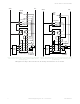
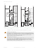
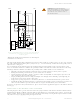
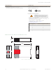
Table Of Contents

and electromechanical valves. If your machine documentation leaves any doubt about the proper connection points for the
Interface Module output contacts, do not make any connections. Contact the machine builder for clarification regarding
connection to the MPCEs.
Two-Channel Control: Two-channel control allows the Primary Safety Device to detect an unsafe failure of the control
wires. Two-channel control should be used whenever unsafe failure of the control wires cannot be eliminated.
The outputs of the primary safety device must at minimum, comply with the requirements described on page 5. These
outputs must be monitored for failure by the primary safety device. In addition, a single output failure cannot prevent
normal stopping action, and a successive cycle cannot be initiated until the failure has been corrected.
NOTE: NOTICE regarding MPCEs To achieve control reliability, two Machine Primary Control Elements (MPCEs) are
required to control each machine hazard. Each MPCE must be capable of immediately stopping the dangerous
machine motion, irrespective of the state of the other. Some machines offer only one primary control element. For
such machines, it is necessary to duplicate the circuit of the single MPCE to add a second MPCE.
MPCEs must offer at least one forced-guided auxiliary contact which is wired to the monitoring contact
feedback input of the primary safety device (see hookup diagrams).
WARNING: Interfacing MPCEs.
NEVER wire any intermediate device(s) (e.g., PLC, PES, PC), between the Interface Module outputs and
the Machine Primary Control Elements (MPCE1 to MPCE3) it switches, in such a manner that in the
event of a failure there is the loss of the safety stop command, OR in such a manner that the safety
function can be suspended, overridden, or defeated, unless accomplished with the same or greater
degree of safety. Whenever forced-guided, mechanically linked relays are added as intermediate
switching devices, a normally closed forced-guided monitor contact from each relay must be added to
the series feedback loop between Interface Module terminals Y1, Y2, Y3, and Y4.
Initial and Periodic Checkout Procedure
The Interface Module can be used safely only when its operation is controlled via an appropriate primary safety device,
connected to the Interface according to the wiring diagrams shown in the wiring diagrams.
CAUTION: Disconnect Power Prior to Checkout
Before performing the initial checkout procedure, make certain all power is disconnected
from the machine to be controlled.
Dangerous voltages may be present along the Safety Module wiring barriers whenever power to the
machine control elements is On. Exercise extreme caution whenever machine control power is
or may be present. Always disconnect power to the machine control elements before opening
the enclosure housing of the Safety Module.
The functioning of the Safety Module and the device(s) connected to it must be verified at initial installation and on a
regular periodic basis to ensure proper operation (see also the machine manufacturer's recommendations).
1. Remove the power controlling (and switched by) the machine control elements (see Caution).
2. Verify the primary safety device that will be controlling the Interface Module is operating correctly, according to its
product documentation and manufacturer’s recommendations.
3. Confirm proper connection of the Interface Module to the controlling primary safety device according to the wiring
diagram.
4. Verify all Interface Module output contacts follow exactly the operation of the safety output contacts of the controlling
primary safety device, when the primary safety device is operated according to its product documentation and
manufacturer’s recommendations.
Repairs
Contact Banner Engineering for troubleshooting of this device. Do not attempt any repairs to this Banner device; it
contains no field-replaceable parts or components. If the device, device part, or device component is determined to
be defective by a Banner Applications Engineer, they will advise you of Banner's RMA (Return Merchandise Authorization)
procedure.
Important: If instructed to return the device, pack it with care. Damage that occurs in return shipping is not
covered by warranty.
IM-T-9A and IM-T-11A Interface Modules
8 www.bannerengineering.com - Tel: +1-763-544-3164 P/N 62822 Rev. F