
Cut Sheet

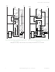
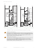
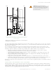
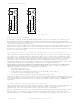
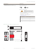
Table Of Contents

Y2
Y1
Y3
13 14
23 24
33 34
IM-T-9A
Y4
S3
K2
S4 S2
K1
S1
Y2
Y1
Y3
13 14
23 24
IM-T-11A
Y4
S3
K2
S4 S2
K1
S1
31 32
Figure 8. Interface Module Pinouts
External Device Monitoring
To satisfy the requirements of Control Reliability (OSHA and ANSI), Category 3 and 4 of ISO 13849-1 (EN 954-1), the
Machine Primary Control Elements (MPCEs) must each offer a normally closed, forced-guided (mechanically linked)
monitor contact. Connect one normally closed monitor contact from each Machine Primary Control Element as shown in the
appropriate hookup drawing (on previous pages).
In operation, if one of the switching contacts of either MPCE fails in the energized condition, the associated monitor contact
will remain open. Therefore, it will not be possible to reset the Primary Safety Device. If no MPCE-monitor contacts are
monitored, it is the user's responsibility to ensure that any single failure will not result in a hazardous condition and will
prevent a successive machine cycle.
Overvoltage Category II and III Installations (EN 50178 and IEC 60664-1)
The Safety Module is rated for Overvoltage Category III when voltages of 1 V to 150 V ac/dc are applied to the output
relay contacts. It is rated for Overvoltage Category II when voltages of 151 V to 250 V ac/dc are applied to the output
relay contacts and no additional precautions are taken to attenuate possible overvoltage situations in the supply voltage.
The Module can be used in an Overvoltage Category III environment (with voltages of 151 V to 250 V ac/dc) if care is
taken either to reduce the level of electrical disturbances seen by the Module to Overvoltage Category II levels by
installing surge suppressor devices (for example, arc suppressors), or to install extra external insulation in order to isolate
both the Safety Module and the user from the higher voltage levels of a Category III environment.
For Overvoltage Category III installations with applied voltages from 151 V to 250 V ac/dc applied to the
output contact(s): the Safety Module may be used under the conditions of a higher overvoltage category where
appropriate overvoltage reduction is provided. Appropriate methods include:
• An overvoltage protective device
• A transformer with isolated windings
• A distribution system with multiple branch circuits (capable of diverting energy of surges)
• A capacitance capable of absorbing energy of surges
• A resistance or similar damping device capable of dissipating the energy of surges
When switching inductive ac loads, it is good practice to protect the Safety Module outputs by installing appropriately-sized
arc suppressors. However, if arc suppressors are used, they must be installed across the load being switched (for example,
across the coils of external safety relays), and never across the Safety Module’s output contacts (see WARNING, Arc
Suppressors).
Auxiliary Monitor Contact (Model IM-T-11A Only)
The action of the auxiliary monitor contact, terminals 31-32, inversely "follows" the action of the safety outputs. The 31-32
auxiliary monitor contact is to be used only for control functions that are NOT safety-related. A typical use is to
communicate the status of the Safety Module output to a programmable logic controller (PLC).
Many types of mechanisms are used to arrest dangerous machine motion. Examples include mechanical braking systems,
clutch mechanisms, and combinations of brakes and clutches. Additionally, control of the arresting scheme may be
hydraulic or pneumatic. As a result, an MPCE may be one of several control types, including a wide variety of contactors
IM-T-9A and IM-T-11A Interface Modules
P/N 62822 Rev. F www.bannerengineering.com - Tel: +1-763-544-3164 7