
Cut Sheet

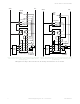
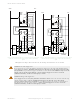
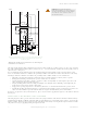
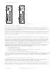
Table Of Contents

WARNING: Not for use as a stand-alone safety module.
1. DO NOT connect E-stop switches, 2-hand control actuators/switches, safety interlock switches, or similar
devices directly to this Interface Module.
2. ALWAYS connect terminals Y1-Y2 and Y3-Y4 of this Interface Module to the monitoring input of the primary
safety device that controls it.
This Module does not have the circuitry required to perform a self-check. A single fault inside the unit or
in external devices (like switches or E-stop buttons) can go undetected and create an unsafe condition.
Failure to properly connect this Interface Module to a primary safety device with a monitoring function
could result in serious injury or death.
Mechanical Installation
The Safety Module must be installed inside an enclosure.
It is not designed for exposed wiring. It is the user’s responsibility to house the Safety Module in an enclosure with NEMA 3
(IEC IP54) rating, or better. The Safety Module mounts directly to standard 35 mm DIN rail.
Heat Dissipation Considerations: For reliable operation, ensure that the operating specifications are not exceeded. The
enclosure must provide adequate heat dissipation, so that the air closely surrounding the Module does not exceed the
maximum operating temperature stated in the Specifications. Methods to reduce heat build-up include venting, forced
airflow (for example, exhaust fans), adequate enclosure exterior surface area, and spacing between modules and other
sources of heat.
Electrical Installation
CAUTION: Shock Hazard
Always disconnect power from the Banner device and the guarded machine before making any
connections or replacing any component. Electrical installation and wiring must be made by qualified
personnel and must comply with the NEC (National Electrical Code), ANSI NFPA79 or IEC 60204-1 and
-2, and all applicable local standards and codes. Use extreme caution to avoid electrical shock at
all times. Serious bodily injury or death could result.
WARNING: Risk Assessment
The level of safety circuit integrity can be greatly affected by the design and installation of the safety
devices and the means of interfacing of those devices. A risk assessment must be performed to
determine the appropriate level of safety circuit integrity to ensure the expected risk
reduction is achieved and all relevant regulations and standards are complied with.
CAUTION: When FSD1 switches +24 V dc and FSD2 switches 0 V dc (Figures 4 and 5), a short circuit between the
wires leading to S1, S2, S3 and S4 is detected immediately and K1 and K2 de-energize. However, a short circuit
can result in a high current through the FSD1 and FSD2 contacts, so the current coming from the 24 V dc supply
connected to FSD1 and FSD2 must be fused or limited to 6 amps max. Otherwise, damage to the primary safety
device may result.
It is not possible to give exact wiring instructions for a Safety Module that interfaces to a multitude of machine control
configurations. The following guidelines are general in nature.
The Safety Module has no delay function. Its output relay contacts open within 20 milliseconds after a safety input
opens. This classifies the Safety Module as functional stop "Category 0" control, as defined by ANSI NFPA 79 and IEC/EN
60204-1.
The inputs can be connected to (that meet the requirements for primary safety device above):
• A +24 V dc solid-state (PNP) outputs in single-channel or dual-channel hookup configuration, or
• A +24 V/0 V dc source that is switched by hard/relay contacts in single-channel or dual-channel hookup
configuration.
The dual-channel hookup configuration allows the primary safety device to detect certain failures and faults, such as short
circuits, that could result in a loss of the safety function. Two-channel control should be used whenever unsafe failure of
the control wires cannot be eliminated. The first circuit shown below can meet ISO 13849-1 Category 2, 3, or 4
requirements, depending on the safety rating and the installation of the primary safety device.
The outputs of the primary safety device must, at minimum, comply with the requirements described. These outputs must
be monitored for failure by the primary safety device. In addition, a single output failure cannot prevent normal stopping
action, and a successive cycle cannot be initiated until the failure has been corrected.
IM-T-9A and IM-T-11A Interface Modules
P/N 62822 Rev. F www.bannerengineering.com - Tel: +1-763-544-3164 3