
User Manual


97229 v.8.0 15
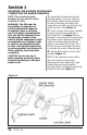
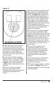
4. With the alcohol swab from your
kit, clean the suction cup and the
mounting area and let dry. With the
suction lever in the up position ensure
the suction cup is flat against the
windshield or smooth, flat surface.
Then, push the suction lever down to
secure in place.
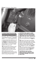
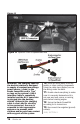
5. Find the Banks OBD II Interface
Cable in your kit. Connect the Banks
Interface Cable to the vehicle’s OBD II
connector. Use a cable tie as shown
in Figure 13 to secure the Banks
Interface Cable to the vehicle’s OBD II
connector.
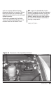
6. Next, connect the 6-terminal
connector on the Banks OBD II
Interface Cable to the 6-pin connector
on the Banks SpeedBrake wire
harness.
NOTE: If your vehicle is equipped with a
Banks Diesel Tuner, Optional Tuner-to-
SpeedBrake cable will be needed (P/N
55412). See Figure 14. Disconnect the
6-pin terminal connections between
Banks OBD II Interface Cable and Banks
Diesel Tuner. Connect the OBD II 6-pin
male connector to the optional Tuner-
to-SpeedBrake 6-pin female connector.
Connect the two (2) wire male connector
to the SpeedBrake female 6-pin
connector and connect the four (4) wire
male connector to the Diesel Tuner
female 6-pin connector.
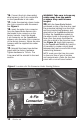
7. Route the RJ12 connector (phone
like connector) on the Banks OBD II
Interface Cable under the dash and out
where the fuse access panel was. See
Figure 6. The RJ12 connectors’s cable
can be slid under the door frame’s
seal and run up to the top of the dash.
Plug the RJ12 connector into one of
the receptacles in the base of the PDA
docking station. Re-install the fuse
access panel.
8. Your Docking Station is now
installed and is ready for the
Banks PowerPDA. Install the Banks
PowerPDA into the Docking Station.
Be sure the Banks PowerPDA is
completely seated in the Docking
Station against the lower support
bracket.
NOTE: There may be a snug fit when
installing the PowerPDA into the
docking station. Do not apply force
during PDA installation.
9. Plug the docking station’s charging
cable (seen in Figure 11) into the
charging receptacle on the lower edge
of the PowerPDA.
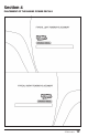
Figure 12