
User Manual

10 97227 v.7.0
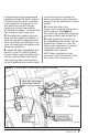
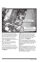
13. Position the electrical center back
in place until the tabs snap into place.
NOTE: adjust the C100 connection
under the electrical center to have
sufficient room to lock the electrical
center back in place. Run the wire
harness out to the firewall side of the
fuse brace. See Figure 6.
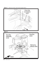
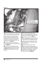
14. Locate mini-fuse for the Body
Control Module (TBC IGN1) and remove
it. See Figure 7.
15. Install the mini-blade fuse tap
onto the removed mini fuse as shown
in Figure 8. Re-install the mini fuse
with the attached blade tap into the
fuse box.
NOTE: install the fuse tap in the
Body Control Module (TBC IGN1) spot
closest to the firewall. This is the “hot”
side of the circuit. See Figure 7.
16. Locate the fuse connector wire
on the SpeedBrake wiring harness and
connect it to the mini-blade fuse tap.
Replace the fuse box assembly cover
and make sure not to pinch the fuse
connector wire.
17. Replace the fuse box cover.
18. Locate the black wire harness
locking connectors between the brake
fluid reservoir and the air conditioning
compressor. Lift the gray connector
locks and disconnect the 24-pin
connector pair. See Figure 9.
Figure 6