InstallationManual Banks SpeedBrake For use with Palm® Tungsten™ E2 2004-2005 Chevy/GMC 6.6L (LLY) Turbo-Diesel Pickup THIS MANUAL IS FOR USE WITH KITS 55419 & 55421 Gale Banks Engineering 546 Duggan Avenue • Azusa, ca 91702 (626) 969-9600 • Fax (626) 334-1743 Product Information & Sales: (888) 635-4565 bankspower.com ©2012 Gale Banks Engineering 03/05/12 PN 97223 v.2.
Do not use this product until you have carefully read the following agreement. This sets forth the terms and conditions for the use of this product. The installation of this product indicates that the BUYER has read and understands this agreement and accepts its terms and conditions. Disclaimer of Liability Gale Banks Engineering Inc., and its distributors, employees, and dealers (hereafter “SELLER”) shall in no way be responsible for the product’s proper use and service.
Limitation of Warranty Gale Banks Engineering Inc. (hereafter “SELLER”), gives Limited Warranty as to description, quality, merchantability, fitness for any particular purpose, productiveness, or any other matter of SELLER’s product sold herewith. The SELLER shall be in no way responsible for the product’s open use and service and the BUYER hereby waives all rights except those expressly written herein. This Warranty shall not be extended or varied except by written instrument signed by SELLER and BUYER.
General Installation Practices Dear Customer, Your new Banks SpeedBrake is a uniquely designed braking system with electronic controls, designed to achieve the optimum level of braking from your vehicle’s engine. If you have any questions concerning the installation of your Banks SpeedBrake System, please call our Technical Service Hotline at (888) 839-2700 between 7:00am and 5:00pm (PST).
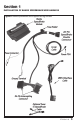
Section 1 Installation of Banks SpeedBrake wire harness Figure 1 Banks SpeedBrake and supplied wiring harness 97223 v.2.
1. Before beginning the SpeedBrake installation, locate The Palm Tungsten E2 Power PDA in your kit. It will need to be charged for a minimum of one hour before the unit will function. Charge the unit with the supplied AC-outlet wall charger. The unit will be fully charged in one to two hours. 2. Disconnect the negative (ground) cable from the battery (or batteries, if there are two) before beginning work.
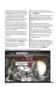
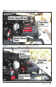
Figure 2 Electrical Center Fuse Tap Location Figure 3 Fuse Tap Installation 97223 v.2.
11. Insert the male 24 pin connector on the SpeedBrake harness into the female 24-pin connector on the factory harness. Insert the female 24-pin connector on the SpeedBrake harness onto the male 24-pin connector of the factory harness. Note: If vehicle is equipped with a Banks Tuner, disconnect the 24-pin connection between the factory 24-pin connectors and the Banks Tuner 24-pin connectors. It is not important if the intercepting connection is made before the Banks Tuner connection or after.
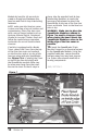
Figure 5 Placement of Banks Tuner on top of the Fuse Box. Figure 6 Placement of Banks Tuner on side of the Fuse Box. 97223 v.2.
Module by hand for 60-seconds to create a strong bond between the fuse box and hook & loop interlocking fasteners. Note: make sure the fuse box cover is clean and free of any oil residue and contaminates. Clean fuse box cover with a non-oil based solvent such as Acetone, Mineral Spirits, Denatured Alcohol or Lacquer Thinner. Read and follow the manufactures operation instruction for non-oil based solvent cleanser.
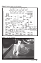
Section 2 MOUNTING THE DOCKING STATION AND CONNECTING THE BANKS POWERPDA Note: This system has been designed for use with the Palm Tungsten E2 PDA. 2. Find a smooth, flat surface suitable for ease of access and viewing of the PowerPDA. See Figure 9 for an example. Loosen both knobs and move the swivel suction plate and docking station to achieve desired viewing angle of the PowerPDA screen. Do a test fit and note the angle necessary to achieve the correct viewing angle.
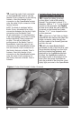
Figure 9 Fuse Access Panel Figure 10 5. Find the Banks OBD II Interface Cable in your kit. Connect the Banks Interface Cable to the vehicle’s OBD II connector. Use a cable tie, as shown in Figure 11, to secure the Banks Interface Cable to the vehicle’s OBD II connector. 6. Next, connect the 6-terminal connector on the Banks OBD II Interface Cable to the 6-pin connector on the Banks SpeedBrake wire harness.
Figure 11 connector to the SpeedBrake female 6-pin connector and connect the four (4) wire 6-pin male connector to the Diesel Tuner female 6-pin connector. 7. For the cleanest PowerPDA installation (Figure 9), remove the fuse access panel by pulling it out from the side of the dash. Route the RJ12 connector (phone like connector) on the Banks OBD II Interface Cable under the dash and out where the fuse access panel was.
Figure 12 Optional Tuner-to-SpeedBrake wire WARNING: The charging cable on the docking station is designed to supply a constant low-voltage power source (+5vdc) to the Banks PowerPDA and is “live” as long as the system’s OBD II Interface Cable is completely installed and the RJ12 connector is plugged into the docking station.
Section 3 Banks SpeedBrake PowerPDA Software & Installation Figure 13 Front view Power HOME KEY MENU KEY 5-WAY NAVIGATOR Center Button 97223 v.2.
The SpeedBrake PowerPDA software is supplied on a Secure Digital (SD) media card. The software should be installed on the Palm Tungsten E2 and run from main memory. You can use the additional space on the SD card to store music, photos and other data. Refer to your device instruction manual for using SD cards to store data. You should leave a copy of the SpeedBrake PowerPDA software on the SD card as a backup for future reference. 3. In the ‘Copy From’ drop down menu 1.
Figure 16 Figure 18 Shown with Tuner program installed. Figure 17 97223 v.2.
Section 4 PLACEMENT OF THE BANKS POWER DECALS 18 97223 v.2.
Notes 97223 v.2.
Gale Banks Engineering 546 Duggan Avenue • Azusa, ca 91702 (626) 969-9600 • Fax (626) 334-1743 Product Information & Sales: (888) 635-4565 bankspower.