
Instruction Manual

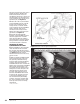


2. Cut out the supplied template (see
Figure 46) and align the template
onto the rear of the IP, squarely
seating it on the top of the IP
mounting pin (see Figure 47).
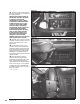
3. Using a
3
⁄8” Uni-bit, center the
bit onto the
3
⁄8” drill location on the
template and slowly drill through the
IP. Using a
1
⁄8” drill bit, center and
drill through the
1
⁄8” location on the
template. Remove and discard the
template and any plastic shavings.
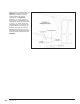
4. On the front side of the IP, align
the Power Level Selector Switch label
onto the previously drilled hole (see
Figure 48).
Figure 47
36 96776 v.11.0