
Instruction Manual
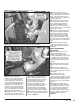

1. The thermocouple monitors
the temperature of the exhaust
gases entering the turbocharger
at the turbine housing. Installation
requires that the exhaust manifold
be drilled near the manifold outlet.
It is recommended that the manifold
be removed from the engine to
thoroughly clean out all metal chips
from drilling. If manifold is not
removed from the vehicle, all chips
must be removed from the manifold.
This may be accomplished by using
a magnet to extract the chips after
drilling. The tap should be greased
before use and the chips again
removed with a magnet. All metal
shavings must be cleaned from the
manifold to avoid turbine damage.
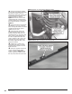
2. Remove passenger side wheel
well.
3. On the passenger side, remove
the hardware retaining the turbine
inlet exhaust pipe to the exhaust
manifold using a 12mm, 12pt socket
along with a 12mm, 12pt wrench,
then remove the exhaust manifold
from vehicle. Pay special attention to
the orientation of the manifold outlet
gasket. Retain the hardware and
gaskets for re-assembly.
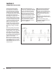
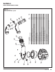
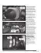
4. Center punch and drill through
the passenger side exhaust manifold
into the rear passage at the location
shown Figure 23. Use a
7
⁄16” drill,
keeping the drill perpendicular to the
manifold surface.
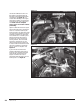
5. Tap the drilled hole with a
1
⁄4”
NPT pipe tap. Check the thread depth
as you tap by periodically removing
the tap and screwing the thermo-
couple insert into the tapped hole.
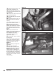
6. Install the thermocouple insert
into the manifold using anti-seize
compound on the threads. Install the
probe in the thermocouple insert.
7. Make sure to remove all shavings
from inside the exhaust manifold.
Reinstall the exhaust manifold.
Torque to 28 ft-lb in the sequence
shown see Figure 23.
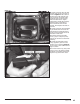
8. Attach the thermocouple to the
supplied thermocouple leadwire
extension with the supplied nuts
and bolts. Cover this joint with the
supplied heat shrink tubing and heat
until the tubing conforms to the
joint. Make sure the entire joint is
insulated.
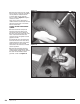
9. Route the thermocouple leadwire
extension along the factory harness to
the driver’s side.
Note: The thermocouple will be
connected to the EconoMind harness
in Section 5, Step 5.
-END, SECTION 3-
Section 3
THERMOCOUPLE INSTALLATION
Figure 23
24 96776 v.11.0