
Instruction Manual
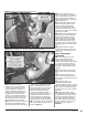
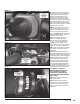

40. Install the upper fan shroud. The
supplied gasket is used to fill the gap
between the shroud and the cross
brace. The push-in retainers that
secure the upper shroud to the lower
shroud are secured by inserting the
retainer with the center pin pulled
out. Once the retainer is inserted,
press the center pin down to secure
the retainer. Install the gasket and
upper fan shroud bolts. The stock
upper fan shroud bolts are reused
and should be tighten to 80 in-lbs.
41. Install the a/c condenser and
tighten it’s upper mounting bolts to
80 in-lbs
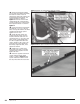
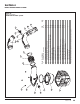
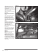
42. Install the latch support. Tighten
it’s six attachment bolts to 80 in-lbs.
Install the oil-cooler-line retaining clip
shown in Figure 13.
43. Install the hood latch. Position it
so that it aligns with the marks that
were previously made on the latch
support prior to it’s removal. Tighten
it’s bolts to 80 in-lbs.
44. Install the driver and passenger
side plastic headlamp support
structures. Tighten the screws to 80
in-lbs.
45. Install the light bulbs into the
park/turn signal lamp assemblies.
These are held in place by turning
them clockwise. Install the park/
turn signal lamp assembly onto
the vehicle for both the driver and
passenger side.
46. Install the electrical connectors
to the headlamp assembly. Install
the headlamp assemblies and secure
them with their retaining pins.
47. Install the grill:
a. 2001 to 2002 vehicles: The grill is
retained by (4x)
1
⁄4 turn fasteners,
(1x) screw at the latch support, and
(2x) clips at the outboard ends of the
grill. Tighten the screw at the latch
support to 75 in-lbs.
b. 2003 to 2005 vehicles: The grill is
held in place by retaining clips, and
can be snapped in place.
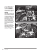
48. Install the upper grill baffle
and secure with the seven push-
in retainers that were previously
removed. The push-in retainers that
secure the grill baffle are secured by
inserting the retainer with the center
pin pulled out. Once the retainer is
inserted, press the center pin down
to secure the retainer.
NOTE: Before slipping any boost
tubes and the corresponding
hoses, into position, ensure that all
connection ends are clean and free
of any oil residue and contaminates.
Clean compressor outlet and all
connection points with a non-oil
based solvent such as Acetone,
Mineral Spirits, Denatured Alcohol or
Lacquer Thinner. Read and follow the
manufactures operation instruction
for non-oil based solvent cleaner.
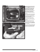
49. Install the driver and passenger
side boost tubes. New clamps are
provided for the intake manifold
hose to boost tube connection
and the turbo hose to boost tube
connection. All other locations reuse
the factory clamps. Tighten the
clamps to 75 in-lbs. The following
hoses are used at each location:
2001 vehicles:
Turbocharger outlet: 3 inch to 2
3
⁄8
inch ID straight reducer
CAC inlet (driver side): Re-use factory
hose
CAC outlet (passenger side): Uniform
3 inch ID with 145-degree bend
Intake manifold: 3 inch to 2
3
⁄8 inch ID
with 120-degree bend
2002 to 2004 LB7 vehicles:
Turbocharger outlet: 3 inch to 2
3
⁄8
inch ID straight reducer
CAC inlet (driver side): Re-use factory
hos
CAC outlet (passenger side): Re-use
factory hose
Intake manifold: 3 inch to 2
3
⁄8 inch ID
straight reducer
2004.5 to 2005 LLY vehicles:
Turbocharger outlet: 3 inch to 2
3
⁄8
inch ID straight reducer.
CAC inlet (driver side): Re-use factory
hose.
CAC outlet (passenger side): Uniform
3 inch ID with 145-degree bend.
Intake manifold: 3 inch to 2
3
⁄8 inch ID
with 120-degree bend.
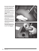
50. Install the driverside wheel well.
Install the lower air cleaner support
bracket. Tighten the bolts to 80
in-lbs. Do not reinstall the air cleaner
mounting tray. It will not be reused.
However, the fasteners will be used
for installation of the Ram-Air filter
housing.
-END, SECTION 2-
96776 v.11.0 23