
Instruction Manual
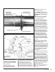
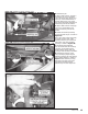

13. Insert the intermediate pipe
inlet onto the flanged intermediate
pipe outlet. Install the intermediate
pipe hanger pin(s) into the vehicle
rubber grommets.
NOTE: Once the pipe has been
completely engaged in the slip
joint, it should be marked with a
marker, scribe or tape for reference
when tightening clamps later in the
installation. Each slip joint in the
system should be marked in this
fashion. When the exhaust system is
being adjusted to align the hangers,
the slip joints can be adjusted so that
the reference mark is no more than
1
⁄4” away from its original position.
Step 14 thru 21 applies only to
single tailpipe systems.
Skip to Step 22 if installing Banks
Split-Dual Monster Exhaust System.
Single Tailpipe System (Step 14
thru 21)
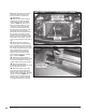
14. Slide one (1) of the supplied
4-inch exhaust clamps over the
Banks intermediate pipe.
Note: On extended cab long-bed
and crew-cab long-bed vehicle, the
clamp that is used between the
intermediate pipe and muffler is a
combination hanger/clamp. When
this hanger clamp is installed the
hanger pin should be inserted into
the factory rubber hanger and the
clamp should be rotated until the
hanger pin is parallel with the frame-
mounted pin before being torqued.
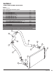
15. Install the muffler onto the end
of the intermediate pipe outlet. Be
sure that the inlet side of the muffler
(see markings on muffler body)
is facing toward the front of the
vehicle. Orient the muffler such that
the “Banks Monster” logo is facing
towards the frame and is level with
the ground. Verify that the muffler
and intermediate pipe are completely
engaged.
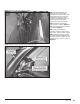
16. Slide one (1) of the supplied
4” exhaust clamps onto the Banks
Monster muffler outlet.
17. Install the tailpipe into the outlet
of the muffler. Be sure that the two
pipes are completely engaged. Insert
the front and rear tailpipe hanger
pins into the factory rubber hangers.
Rotate the tailpipe until the hanger
pins are parallel with the frame
mounted pin.
NOTE: Minimum distance between
exhaust tip and body a half (
1
⁄2) inch.
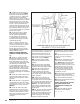
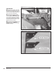
18. Adjust each of the pipes to
ensure that all of the hanger pins
are parallel with the frame-mounted
pins and that the rubber hangers are
all positioned slightly forward (See
Figure 3). The amount of forward
angle on the rubber hangers should
increase the farther downstream the
hanger is positioned. This allows the
hangers to be properly positioned
once the exhaust system reaches
operating temperature.
19. Tighten the head pipe V-band
clamp to 12 ft-lbs (if previously
loosened).
Figure 4
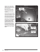
Figure 5
96776 v.11.0 11