
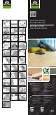
Installation Guide

EN
READ THIS MANUAL CAREFULLY BEFORE IN-
STALLING THE FLOOR.
NON-COMPLIANCE WITH THE GUIDANCE
WILL MAKE THE GUARANTEE VOID.
THE INSTALLER/CONTRACTOR IS THE ULTI-
MATE QUALITY INSPECTOR AND SHOULD
NOT INSTALL BOARDS WHICH BEAR VISIBLE
DEFECTS OR OTHER FEATURES WHICH WILL
BE REJECTED BY THE INVESTOR.
THE MANUFACTURER’S GUARANTEE WILL BE-
COME VOID IF ANY BOARDS WITH PROBLEMS
ARE INSTALLED.
The three-layer engineered oor must be
stored in a horizontal position in a dry place
and on a level ground in the original sealed
packaging and under certain conditions.
(Fig. 1)
2G adhesive-free installation systems are in-
tended for both oating and substrate-glued
installations.
In newly-erected buildings, the installation of
the oor must be performed as the last nish
jobs. The rooms must be dried to meet the re-
quired climatic conditions.
Boundary climatic conditions maintained for
a longer time perspective or exceeded with
regard to recommended values – both during
the assembly and use of the oor may lead to
deformations – lateral bending, which is a nat-
ural response of timber.
Suboor
The three-layer oor should be installed on
a concrete, anhydrite or wooden and wood-
like suboor.
The suboor should be even, at and dry, and
should not crumble. The unevenness of the
oor must not exceed applicable standards.
(Fig. 2)
Before the three-layer installation is begun, the
suboor humidity must be checked and doc-
umented:
- for concrete suboors < 2% CM,
- for concrete suboors with oor heating
<1,8% CM,
- for anhydrite < 0.5% CM,
(CM = humidity measured using carbide
method)
- for wooden suboors < 10% RH. (Fig. 3)
In the case of a oating oor, a damp-proof
material (PE lm) and sound insulation mate-
rial (e.g. foam of suitable thickness) should be
used. The lm should overlap while the foam
should be butted. (Fig. 4)
In the case of gluing the oor to the suboor,
the installation must comply with the follow-
ing parameters:
- stripping strength min. 1.5 MPa,
- compression strength min. 25-30 MPa,
- shearing strength min. 3.5 MPa.
Floor heating
The three-layer oor is used for installing over
oor heating subject to the conditions listed
below.
- The maximum temperature of the oor sur-
face must not exceed 27
o
C. (Fig. 5)
- The electrical system must feature a gradual
temperature increase system.
- The suboor construction must provide
an even spread of heat.
- Installation of the three-layer oor over
a suboor which is only partially tted with
oor heating is forbidden. (Fig. 6, 7)
- A suboor with a heating system must be
warmed up and the process must be docu-
mented. (Fig. 8)
- If the installation is performed during the
heating season, the system must not be on.
The heating should be switched o at least 4
hours before the installation begins.
Caution!
Three-layer oors whose top layers are made of
beech, maple, jatoba, northern red oak, badi or
tali cannot be installed over oor heating.
INSTALLATION
Depending on the natural uctuation of the
wooden oor humidity, and because of low
air humidity, it is impossible to avoid the
emergence of gaps between three-layer oor-
boards, even though they are glued. The emer-
gence of gaps in the three-layer oor is not
considered a aw.
Assembly tools and materials: a pencil, a knife,
a wood cutting saw, a drill, a chisel, a tape
measure, a wooden block or a mallet.
General principles
- In long and narrow rooms (e.g. corridors), sol-
id boards should be installed lengthwise and
they should be aligned with the direction of
the main source of light. (Fig. 9)
- You should keep a min. 10 mm gap between
the outer oor edges and xed building el-
ements (walls, doors, thresholds, pipes etc.)
for a 6-metre-long oor. If the oor is longer,
increase the dilatation by 1.5 mm per each
additional metre of oor. (Fig. 10, 11)
- Divide oors whose surface is bigger than
100 m
2
and or 10 linear metres in width. Cov-
er the gap with a wood strip. (Fig. 10)
- If the oor will extend into several rooms,
divide the boards at the door openings.
Gluing down to the suboor requirements
determines the area and layout of the oor
and used adhesive systems because of the
exibility (for assessment by the installer).
You should use dilatation for a oating in-
stallation.
- If the room is of a complicated shape (L-, F-,
T-, U-), it is recommended to divided the oor
– in particular for the oating oor.
- The rst and the last row – the minimum
width should not be less than 50 mm. (Fig. 12)
Caution!
A batch may include boards shorter as much as
30 mm on the 1.5% scale.
Installation 2
- Place the rst board with the tongue facing
the wall. Put the installation wedge between
the board and the wall. (Fig. 13)
- Insert the second board into the end prole
of the rst at approx. 20° and push down
to lay it at. If the board resists signicantly
while being pushed down, check the prole
for the presence of foreign bodies. Continue
until the rst row is complete. (Fig. 14)
- Cut o the last board so as to leave an appro-
priate gap (expansion gap) by the wall. The
last board should be at least 300mm long.
Begin the next row with the cut-o piece of
board from the previous row. It is advisable
to apply overlaps of approx. 300 mm be-
tween the joints. The rst board in the row
should have the same minimum dimension
(Fig. 15)
- If the wall is uneven, draw the curvature line
on the board in the rst row and cut it ac-
cordingly (Fig. 16)
- Laying the next row. Insert the rst board for
next row board into the side prole of the
previous row at approx. 20°. Chock the right
hand end of the board being laid so that the
board edge is approx. 2 cm above the sub-
oor. (Fig. 17, 18)
- Connect the next board to the end of the
previous one at approx. 20° and as close to
the side of the previous row board as possi-
ble. Drive home with the striker block, move
the chock under the next board and repeat
to nish the installation. (Fig.19, 20, 21)
- After installing three rows, nally determine
the distance from the walls, taking into ac-
count the minimum dilatation required.
(Fig. 22)
- When cutting the last row of the oor, re-
member about the minimum dilatation re-
quired and the board width.
Joining the oor in the doorway.
Place a piece of the oorboard to the door
frame and cut the door frame to the board
height. Remove a piece of the joint, apply some
glue and install the board. (Fig. 29, 30, 31)
Caution!
In the case of gluing the oor to the suboor,
apply the glue to the suboor little by little,
according to the glue manufacturer’s guide-
lines. Use appropriate adhesive systems and
tools! Having installed a few rows, weigh down
the oor using heavy elements (e.g. unused
boards). (Fig. 32, 33)
Skirting and nishing jobs
Fix the skirting to the wall, never to the in-
stalled oor. (Fig. 34)
Cleaning and care. Precautionary measures
- Use proper doormats in order to remove
sand and other dirt from the shoes. (Fig. 35)
- Use protective chair and furniture leg caps
designed for wooden oors, as well as mats
under chair castors. (Fig. 36)
- Accidentally split water must be immediately
wiped up.
- The oor must not be installed in bathrooms
and similar rooms. (Fig. 37)
Cleaning and care
Varnished oors should be cared for using VAR-
NISHED FLOOR LINE agents on the ooring man-
ufacturer’s oer, in strict accordance with the
instructions to be found on the labels. (Fig. 38)
Oiled oors should be cared for using OILED
FLOOR LINE agents on the ooring manufac-
turer’s oer, in strict accordance with the in-
structions to be found on the labels and apply-
ing the complete system. (Fig.38)
The manufacturer reserves the right to modi-
cations.
ES
LEA DETENIDAMENTE ESTE MANUAL ANTES
DE EMPEZAR LA INSTALACIÓN DEL PISO. EL
INCUMPLIMIENTO DE LAS DIRECCIONES RE-
SULTARÁ LA PÉRDIDA DE LA GARANTÍA.
EL INSTALADOR/CONSTRUCTOR ES EL ÚLTI-
MO INSPECTOR DE CALIDAD Y NO DEBERÍA
INSTALAR TABLAS CON DEFECTOS RECO-
NOCIBLES U OTRAS CARACTERÍSTICAS QUE
PUEDAN ESTAR RECHAZADAS POR EL INVER-
SOR. LA GARANTÍA DEL FABRICANTE EXPIRA
SI SE INSTALARÁN TABLAS DEFECTUOSAS.
El parquet debe dejarse en su embalaje origi-
nal, en posición horizontal, en un lugar seco
y una supercie llana durante un par de días
para que se aclimaten. (Fig. 1)
Los productos con el sistema de anclaje sin
cola están destinados tanto a la instalación
otante como la instalación tradicional con
cola.
En nuevos edicios el suelo debe ser instalado
después de las obras de acabado. Las habita-
ciones tienen que ser secas y ajustadas a las
requeridas condiciones climáticas.
Cuando se supere un límite de las condiciones
climáticas en un largo periodo de tiempo o du-
rante la instalación o el uso del piso, la madera
puede sufrir unas deformaciones que son la
reacción natural.
Sustrato
El parquet debe instalarse sobre los sustratos
como: hormigón, anhidrita o madera. El suelo
debe estar nivelado, asegúrese de que la base
del suelo está plana, limpia, rme, seca y no se
desmorona. La base del suelo no puede pre-
sentar irregularidades por encima de las nor-
mas aceptables. (Fig. 2)
Antes de instalar el piso hay que medir y docu-
mentar la humedad de la supercie:
La comprobación de la humedad de la super-
cie de instalación se realiza con un aparato CM
y no se deben exceder los siguientes valores
límite (Fig. 3):
- para pavimentos de hormigón < 2 CM%,
- pavimentos de hormigón con calefacción
< 1,8 CM%,
- pavimentos de anhidrita < 0.5% CM (me-
dición de humedad usando el método del
carburo),
- pavimentos de madera < 10% RH.
Para la colocación otante es necesario que se
instale un lm anti-humedad de PE así como
un material de amortiguación (p.ej. espuma
con densidad adecuada). Al instalar el lm
anti-humedad hay que superponerlo en las
uniones. La espuma debe estar bien ajustada.
(Fig. 4)
En el caso de encolar, el sustrato tiene que
cumplir los siguientes requisitos:
- adherencia por tracción mínimo 1,5MPa,
- resistencia a la comprensión mínimo 25-30
MPa,
- resistencia al corte mínimo 3,5 MPa
La calefacción por suelo radiante
Parquet de tres capas es adaptado para la ins-
talación sobre la calefacción por suelo radiante
siempre que se cumplan las condiciones si-
guientes:
- La temperatura del supercie no debe exce-
der los 27°C. (Fig 5)
- La calefacción eléctrica debe tener un siste-
ma de subida de temperatura gradual.
- La estructura de base del material debe ser
capaz de distribuir uniformemente el calor.
- Está prohibido instalar el parquet en un sus-
trato, que está equipado con calefacción por
suelo radiante solo en una parte. (Fig. 6, 7)
- El sustrato con el sistema de calefacción debe
ser calentado y este proceso debe ser docu-
mentado. (Fig. 8)
Durante la instalación en el período de cale-
facción, el funcionamiento del sistema de ca-
lefacción está prohíbido. La calefacción debe
estar apagada, como mínimo, 4 horas antes de
empezar la instalación.
Atención!
No se puede instalar el parquet con la capa no-
ble de haya, arce, jatoba, roble rojo, badi y tali.
INSTALACIÓN
Debido a la variación natural de humedad del
piso de madera y debido a la temperatura baja
del aire, no es posible evitar la creación de ra-
nuras entre las tablas del parquet, aunque es-
tén pegadas. La presencia de las ranuras en el
piso de madera no es un defecto.
Herramientas y materiales auxiliares: lápiz,
sierra para madera, taladro, cincel, cinta métri-
ca, cuña de madera o palanqueta.
Principios generales
- En las habitaciones largas y estrechas (p.ej.
pasillos) las lamas deben ser instaladas para-
lelo a la pared más larga y conforme con la
dirección de la luz principal. (Fig. 9)
- Deje una junta de dilatación de 10mm entre
el borde de las lamas y elementos del edicio
(paredes, puertas, umbrales, tuberías, etc.)
para 6m del suelo. Por encima de esta lon-
gitud aumente la dilatación de 1,5 mm por
cada metro adicional. (Fig. 10, 11)
- La supercie del suelo no puede superar 100
m² y/o 10 metros de longitud/anchura. En
este caso las supercies deben ser separados
con ranuras cubiertas con juntas de expan-
sión.
- Si el parquet se expande a otras habitaciones
es recomendable separarlo en la apertura
de la puerta. Al colar el piso al sustrato este
requisito depende de la supercie, la compo-
sición y el sistema adhesivo.
- Si el suelo tiene una forma compleja (L-, F-, T-,
U-) se recomienda separarla – especialmente
en el sistema otante.
- La primera y la última la: la anchura mínima
no debe ser inferior a 50 mm. (Fig. 12)
Atención!
En ciertos lotes pueden encontrarse lamas cor-
tas hasta 30 mm a nivel de 1,5%.
Instalación
- Coloque la primera tabla, con el borde que
tiene la lengüeta apuntando hacia la pared.
Coloque los espaciadores en la abertura entre
la lama y la pared. (Fig. 13)
- Ponga otra lama en perl corto en ángulo de
20° y bájela. En el caso de alta resistencia al
bajar, compruebe si el perl no tiene impure-
zas. Acabe la primera hilera. (Fig. 14)
- Corta la última tabla de modo que se manten-
ga una dilatación adecuada. La última tabla
debería tener una longitud de al menos 300
mm. Empiece la nueva hilera con el sobrante
de la pieza. Se recomienda hacer uniones -
nales de al menos 300 mm. El mismo tamaño
mínimo debería tener la primera lama en la
hilera. (Fig. 15)
- Si la pared no es plana, dibuje una línea de
curvatura en la tabla de la primera la y córte-
la para ajustarla. (Fig.16)
- La la siguiente. Coloque otra lama en el perl
del extremo largo en ángulo de 20°. Ponga la
cuña bajo el lado derecho de la tabla. Deje el
borde de la tabla alrededor de 2 cm por enci-
ma del piso. (Fig. 17, 18)
- Coloque otra lama al extremo corto de la lama
anterior en ángulo de 20° y muy cerca del lar-
go lado de la lama de hilera anterior. Tome
todo con el bloque de ensamblaje. Mueva la
cuña a la tabla siguiente y termina la instala-
ción. (Fig. 19,20, 21)
- Después de instalar tres hileras establece la
distancia nal de las paredes teniendo en
cuenta la dilatación necesaria. (Fig. 22)
- Al cortar la última hilera del piso recuerde los
requisitos de la dilatación y la longitud de la
tabla que hay que cumplir.
La combinación del piso entre la puerta
Coloque una pieza del piso al marco de puerta
y córtalo a la altura de la tabla. Quite el frag-
mento de la junta, aplique la cola e instale la
tabla. (Fig. 29 ,30, 31)
Atención!
En el caso de colar el piso al sustrato aplique
el pegamento gradualmente al sustrato con-
forme con las instrucciones del fabricante de
cola. Use sistemas y herramientas adecuadas!
Después de instalar varias las presione el piso
con objetos duros (p.ej. cajas todavía no insta-
ladas). (Fig. 32, 33)
Rodapiés y acabados de construcciones
Fije los rodapiés a la pared, nunca al piso.
(Fig. 34)
Conservación y mantenimiento. Acciones
preventitivas
- Use felpudos adecuados para remover la are-
na y la suciedad del calzado. (Fig. 35)
- Coloque piezas de eltro bajo las patas de las
sillas y ponga alfombras de protección bajo
las sillas y muebles con ruedas. (Fig. 36)
- Seca el piso inmediatamente en caso de de-
rrame de líquidos.
- El suelo no puede instalado en las habitacio-
nes como el cuarto de baño. (Fig. 37)
Pisos barnizados, limpieza y mantenimiento
Pisos barnizados deben ser cuidados con los
productos dedicados especialmente a LOS PI-
SOS BARNIZADOS de la oferta del fabricante de
los pisos. Usar según las instrucciones escritas
en la etiqueta del producto. (Fig. 38)
Pisos aceitados, limpieza y mantenimiento
Pisos aceitados deben ser cuidados con los
productos de mantenimiento de la oferta del
fabricante del piso para PISOS ACEITADOS.
Usar según las instrucciones escritas en la eti-
queta del producto aplicando el sistema com-
pleto. (Fig.38)
Reclamaciones
La garantía no cubre tablas con defectos reco-
nocibles después de haber sido instaladas. Los
comentarios relativos al envío y el transporte
de este material tienen que ser presentados al
vendedor dentro de siete días de la fecha de
recibir los productos, pero antes de instalar el
piso.
Se reserva la posibilidad de introducir cambios.