
Operating instructions


3
Contents
1. GENERAL NOTES 4
1.1 Explanation of symbols 4
1.2 Safety instructions 4
1.2.1 General safety instructions 4
1.3 Environmental aspects 4
2. TECHNICAL DESCRIPTION 5
2.1 General 5
2.2 EE300Ex labeling 6
2.3 Certification 7
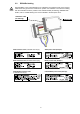
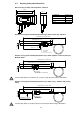
2.4 Housing and probe dimensions 10
2.5 Humidity probe working range 11
2.6 Dewpoint measurement in natural gas 11
2.7 Measurement of moisture in oil 11
3. INSTALLATION IN AN EXPLOSION HAZARD AREA 12
3.1 General 12
3.2 Housing assembly 13
3.2.1 Drilling plan for the housing 13
3.3 Assembly in category 1 (zone 0 / 20); Division 1 14
3.4 Assembly in categories 2 and 3 (Zone 1 2 / 21 22), Division 2 15
3.5 Mounting the measurement sensor 16
3.5.1 Mounting the clamping ring screw connection 16
3.5.2 Mounting with mounting flange (optional) 17
3.5.3 Mounting the probe using ball valve (optional) 18
3.5.4 Mounting the probe using sensor retraction tool (optional) 19
3.6 Calculation of the maximum cable length 20
3.7 Selecting a suitable power supply device for ATEX Zone concept: 20
4. ELECTRICAL CONNECTIONS 22
4.1 Connecting cable 22
4.2 Terminal assignment EE300Ex 23
4.3 Configuration adapter 23
4.4 Calibration of the current loop 23
4.5 Grounding and potential equalization 24
5. DISPLAY (OPTIONAL) 25
6. MAINTENANCE 26
6.1 Filter replacement 26
6.2 Cleaning 26
6.2.1 Cleaning the display 26
6.2.2 Cleaning the sensor 26
6.3 Customer adjustment of humidity and temperature 26
6.4 Ordering information for accessories 26
7. TECHNICAL DATA - EE300EX-HT 27
8. TECHNICAL DATA - EE300EX-xT 28
9. ATEX CERTIFICATE 29
10. EC DECLARATION OF CONFORMITY 34
11. IECEX CERTIFICATE OF CONFORMITY - COC 35
12. FM CERTIFICATE USA 39
13. FM CERTIFICATE CANADA 46
14. CONTROL DRAWING M1_1309080 53