
Operating instructions

25
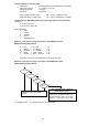
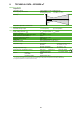
5. DISPLAY (OPTIONAL)
Measured values
Units
Measured values selection top row
Measured values
Measured values selection bottom row
+
-
L+
L-
+
-
+
-
CH2
CH1
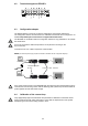
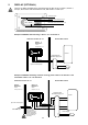
4-20mA ia
Hazardous location T4...T1 Unclassiedlocation
Zone 1 2
Division 2
Class I
Group A, B, C, D
up to IIC or Group A,B
Power supply
Control
Example of EE300Ex wall mounting in Zone 1 or 2 or Division 2
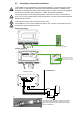
Example of EE300Ex mounting of remote sensing probe in Zone 0 or Division 1 and
transmitter in Zone 1 or 2 or Division 2
There is no display permitted in the gas hazard area for EPL Ga IIC or Class I, Division 1,
Group A, B and in the dust hazard area for IIIA, IIIB and IIIC or Class II, III.
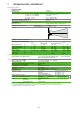
4-20mA ia
4-20mA ia
+
-
L+
L-
+
-
+
-
+
-
+
-
CH2
CH1
Hazardous location T4...T1 Unclassiedlocation
Zone 1 2
Division 2
Class I
Group A, B, C, D
Zone 0
Division 1
Class I
Group A, B, C, D
up to IIC or Group A,B
metalltercaps
Power supply
Control
The bushing must con-
form to the hazard
requirements of a Zone
or Division implementa-
tion. The supplied screw
connection meets this
requirement!
T: 32.25°C
RH: 35.5%
intrinsically safe
transmitter supply unit
intrinsically safe
transmitter supply unit