EE300Ex Series HUMIDITY / TEMPERATURE TRANSMITTER For Intrinsically Safe Applications Operating instructions BA_EE300EX_e // v1.
The operating instructions form part of the equipment supplied and are used to ensure optimal operation and functioning of the device. E+E Elektronik® Ges.m.b.H. provides no warranty of any kind on this publication and no liability for improper use of the products described. To ensure perfect functioning, these operating instructions must be read carefully and observed before the transmitter is commissioned.
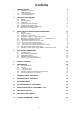
Contents 1. GENERAL NOTES 1.1 1.2 Explanation of symbols Safety instructions 1.3 Environmental aspects 1.2.1 2. 3. 6. General safety instructions 4 4 General EE300Ex labeling Certification Housing and probe dimensions Humidity probe working range Dewpoint measurement in natural gas Measurement of moisture in oil Installation in an explosion hazard area 5 5 6 7 10 11 11 11 12 3.1 3.2 General Housing assembly 3.3 3.4 3.
1. GENERAL NOTES 1.1 Explanation of symbols This symbol indicates safety information. It is essential that this safety information is followed. The manufacturer accepts no liability in the case of contravention. The risk is borne solely by the user. This symbol indicates an instruction. These instructions should be observed to achieve optimum functioning of the device. This symbol indicates regulations that must be observed in hazardous areas at risk of explosion. 1.2 Safety instructions 1.2.
2. TECHNICAL DESCRIPTION 2.1 General The entire EE300Ex transmitter can be installed directly in the explosion hazard area. The EE300Ex is the ideal transmitter in challenging industrial applications. The housing and measurement sensor made from stainless steel, as well as the proven E+E humidity sensors, ensure reliable and stable measurement results over long periods. The EE300Ex has a 2-wire design and has two individually scalable analogue outputs with 4…20mA.
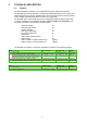
2.2 EE300Ex labeling Each EE300Ex is only characterized for one certificate. The Ordering Code on the Product label shows the type of the Ex Certificate on position “Ex-certificate”. The exact Ex marking with the certificate number is printed on the Hazardous label (Ex marking). EE300Ex with IECEx, USA or Canada labeling must not be installed in the European Union.
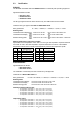
2.3 Certification EUROPE: The EE300Ex transmitter fulfils the ATEX Directives on intrinsically safe operating equipment. Applied standards for ATEX: • EN 1127-1:2011 • EN 60079-0:2012 • EN 60079-11:2012 The EC type approval test has been carried out by TÜV SÜD Product Service GmbH. Certified to EC type approval test TPS 13 ATEX 38892 003 X.
USA: Applied Standard for the U.S. NEC 500, NEC505 and 506: • • • • • • • FM Class 3600 FM Class 3610 FM Class 3611 FM Class 3810 ANSI/ISA 61010-1 ANSI/ISA 60079-0 ANSI/ISA 60079-11 2011 2010 2004 2005 2004 2009 2011 The Certificate of Conformity has been carried out by FM Approvals. Entity parameters: 6.
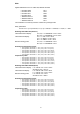
Canada: Applied Standard for Canada CEC Section 18 and Annex J: • CSA 22.2 No. 0-M91 2006 • CSA 22.2 No. 61010-1 2004 • CSA 22.2 No. 157 2006 • CSA 22.2 No. 60079-0 2007 • CSA 22.2 No. 60079-11 2011 • CAN/CSA C 22.2 No. 142-M1987 2004 • CAN/CSA C 22.2 No. 213-M1987 2004 The Certificate of Conformity has been carried out by FM Approvals. Entity parameters: 6.
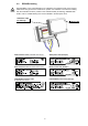
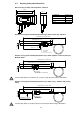
2.4 Housing and probe dimensions Wall mounting humidity and temperature - Model A 179 (7“) 151 (5.9“) 60 (2.4“) Length in mm Stainless steel sinter filter 33 (1.3“) PTFE filter 33 (1.3“) Stainless steel grid filter 39 (1.5“) Oil filter 32 (1.26“) L 53 (2.1“) 98 (3.9“) L = filter cap Remote sensing probe humidity/temperature up to 300 bar (4351 psi) - Model U Cable length acc. to order code 186 (7.32) 15 (0.6“) 15 (0.6“) Probe length 300 (11.8") 12 (0.
Wall mounting temperature - xT model 179 (7“) 151 (5.9“) 70 (2.8“) 98 (3.9“) 60 (2.4“) Remote sensing probe temperature Cable length acc. to order code Ø6 (0.24“) 150 (6“) 2.5 Single-sided screw connection 1/2" ISO or NPT Humidity probe working range Relative humidity [% rel. hum.] The grey area shows the allowed measurement range for the humidity sensor.
3. Installation in an explosion hazard area 3.1 General The EE300Ex has been certified in accordance with the ATEX 94/9EC Directive, IECEX Scheme, , National Electrical Code (ANSI-NFPA 70 (NEC©) and Canadian Electrical Code (CSA C22.1). Devices in explosion-hazard areas are only permitted for operation in atmospheric conditions ≤ T ≤ 40 °C (104 °F) -20 °C (-4°F) 0.8 bar (12 psi) ≤ p ≤ 1.
3.2 Housing assembly The EE300Ex housing has a two-part construction. • Lower housing section with the connection and earthing terminals. • Upper housing section with the electronics and measurement probe. Upper housing part Lower housing part 3.2.1 Drilling plan for the housing 167 (6.6") 4.5 (0.18") 70 (2.8") The lower housing section is mounted using 4 screws. Screw diameter < 4.5mm (0.18") If the upper housing section is removed from the hazard area, e.g.
3.3 Assembly in category 1 (zone 0 / 20); Division 1 Only intrinsically safe power supply devices are approved to supply EE300Ex in category 1 or Division 1. In areas belonging to gas group IIC or Class I, Division 1, Group A,B, it must be ensured that during installation and operation, the possibility of impact and friction sparks has been excluded in rarely occurring fault situations. Work on open transmitter must only be performed if it is guaranteed that no explosive atmosphere is present.
3.4 Assembly in categories 2 and 3 (Zone 1 2 / 21 22), Division 2 Only intrinsically safe power supply devices and protective barriers are approved to supply EE300Ex in category 2 and 3 or Division 2. No display is permitted in the dust hazard area (Group III) or Class II, III. CH1 and CH2 must be galvanically isolated from one another during operation. The probe for wall mounting is not permitted to be used for Zone or Division bushing.
3.5 Mounting the measurement sensor To mount the transmitter, select a location with stable conditions, i.e. protected against direct sunlight or rain. The measurement probe should be fitted at a location where representative measured values are to be anticipated for the process. Wand / Wall r > 30mm The measurement probe must be mounted horizontally or vertically (downwards). If possible, a drip tray should be placed into position before every installation.
Installation instructions: • Tighten the union nuts finger-tight. • Mark the union nuts at the 6 o' clock position. • Hold the screw connection body tight and tighten the union nuts with 1 ¼ turns to the 9 'o clock position. Assembly with high pressure applications and applications with a high security factor: • Tighten the union nuts until the pipe can no longer be turned by hand or can no longer be moved axially in the fitting. • Mark the union nuts at the 6 o' clock position.
3.5.3 Mounting the probe using ball valve (optional) With ball valve mounting, the system being measured does not need to be emptied or brought to a standstill to mount or remove the probe. Install the sensor head against the flow direction. Metal sealing ring Metal sealing ring It is only permitted to use one ball valve that is approved for use in explosion hazard areas. (included with the ball valve set as standard) (as standard with probe) The process pressure must be below 10bar (145psi).
3.5.4 Mounting the probe using sensor retraction tool (optional) Observe the operating instructions of the sensor retraction tool! It may only be used the sensor retraction tool ZM-WA-025-040-EST or BG-WA-103-045-EST. With the sensor retraction tool 250 bar it may only be used the sensor probe model U. The delivery scope of the sensor probe includes the copper sealing for the Swagelok screw connection.
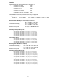
3.6 Calculation of the maximum cable length Intrinsically safe power supply device STAHL 9160/13-11-11 (order code HA011405) Technical data for EE300Ex UBin= 9V + RL * 0.02A Iout max = 20mA Supply voltage: Max. current: Technical data for STAHL 9160/13-11-11 UN = 24V US= 16V RL = 600Ohm Nominal operating voltage: Input voltage for transmitter: Max. load: Calculation of maximum cable length of intrinsically safe input isolator Cable 0.75mm² (0.
Technical data for connecting cable Cable type: ÖLFLEX® EB CY from manufacturer Lapp Kabel Cable cross-section: 4 x 0.75mm² (0.06x0.01in²) Operating capacity: 110nF/km Inductivity: 0.65mH/km Cable capacity for 300m (984ft): Cable inductivity for 300m (984ft): CK = 0.3km * 110nF/km = 33nF LK = 0.3km * 0.65mH/km = 0.
4. ELECTRICAL CONNECTIONS It is essential that installation, electrical connection, commissioning, operation and maintenance in explosion hazard areas are only carried out by trained specialist personnel authorised to do so by the system operator. Installation in accordance with NEC or CEC with consideration of the Control Drawing M1_1309080 For installation in an explosion hazard area, it is essential to ensure that all relevant standards are observed.
CH2 - CH2 + Configuration adapter CH1 - 4.3 CH1 + Terminal assignment EE300Ex Erde 4.2 The digital interface is used only for device configuration and customer adjustment. The configurator software and the drivers are available for download free of charge from our website http://www.epluse.com/en/service-support/download-center/. The EE300Ex in combination with the configurator software is only permitted for use outside the hazard area.
4.5 Grounding and potential equalization The EE300Ex must be integrated into the potential equalization to avoid hazards from electrostatic charges. It shall apply the requirements of the standards EN60079-14, EN60079-25 or IEC60079-14, IEC60079-25. With a remote sensing probe, the probe should also be integrated with the screw connection with a maximum of 1 MΩ in the potential equalization. The ground conductor or the potential equalization connection must have a cross-section of 4mm² (0.
5. DISPLAY (optional) There is no display permitted in the gas hazard area for EPL Ga IIC or Class I, Division 1, Group A, B and in the dust hazard area for IIIA, IIIB and IIIC or Class II, III. Measured values Units T: Measured values selection top row 32.25°C Measured values selection bottom row RH: 35.5% Measured values Example of EE300Ex wall mounting in Zone 1 or 2 or Division 2 Hazardous location T4...
6. MAINTENANCE It is essential that operation and maintenance in explosion hazard areas are only carried out by trained specialist personnel authorised to do so by the system operator. For maintenance and repair work in explosion hazard areas, the standards EN60079-17 or IEC60079-17, EN60079-19 or IEC60079-19 and the relevant national regulations must be applied. In the U.S. maintenance and inspection must be carried out in accordance with ANSI / ISA RP12.6.01-2003 and the NEC.
7. Technical data - EE300EX-ht Measuring values Relative humidity 1) Humidity sensor HC1000 1) 0...100% RH Measuring range Accuracy2) (including hysteresis, non-linearity and repeatability, traceable to international standards, administrated by NIST, PTB, BEV...) ± (1.3 + 0.3%*mv) % RH -15...40°C (5...104°F) ≤90% RH -15...40°C (5...104°F) >90% RH ± 2.3% RH -25...70°C (-13...158°F) ± (1.4 + 1%*mv) % RH ± (1.5 + 1.5%*mv) % RH -40...180°C (-40...356°F) Temperature dependence electronics typ. 0.
8. Technical data - EE300Ex-xT Measuring values Temperature Temperature sensor Measuring range sensor head Accuracy1) Pt1000 (Tolerance class A, DIN EN 60751) wall mounting: -40...60°C (-40...140°F) remote sensing probe: -70...200°C (-94...392°F) ∆°C °C Temperature dependence of electronics typ. 0.
9.
10.
11.
12.
13.
14.
PC PC
HEAD OFFICE: E+E ELEKTRONIK Ges.m.b.H. Langwiesen 7 A-4209 Engerwitzdorf Austria Tel: +43 7235 605 0 Fax: +43 7235 605 8 info@epluse.com www.epluse.com SALES OFFICES: E+E CHINA / BEIJING info@epluse.cn www.epluse.cn E+E CHINA / SHANGHAI info@epluse.cn www.epluse.cn E+E GERMANY info@epluse.de www.epluse.de E+E FRANCE info@epluse.fr www.epluse.fr E+E ITALY info@epluse.it www.epluse.it E+E KOREA info@epluse.co.kr www.epluse.co.kr E+E USA office@epluse.com www.epluse.