
Installation Instructions

TEMPLATE
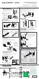
For Drive In Latch
1. Install collar, cylinder, and knob onto exterior chassis.
2. Rotate the collar until the projections on the chassis
align with the grooves on the collar.
3. Push the knob towards the collar and turn set screw
clockwise to secure.
Knob Assembly
(After Rekeying)
1-3/8"
(35 mm)
1-3/4"
(44 mm)
2"
(51 mm)
2-1/4"
(57 mm)
2-1/2"
(64 mm)
Centerline
Ligne médiane
Linea central
Fold
Doble
Plier
2-3/8" 60mm
2-3/4" 70mm
Adjust tang as needed.
47042 / 01
Copyright © 2011 Baldwin Hardware Corporation
OR
Pin
After the completion of Step 1, install the longer turnbutton supplied in the
kit. Proceed to Step 2 and install with longer screws. During Step 4, install
strike supplied in the kit.
THICK DOOR KIT INSTALLATION INSTRUCTIONS
(AVAILABLE SEPARATELY)
Supports 2" (51 mm) up to 2-1/2" (64 mm) doors
Remove existing turnbutton.
Install longer turnbutton.
exterior lever
chassis
OR
exterior knob
chassis
The set screws are pre-installed.
They do not need to be removed
prior to knob/lever installation.
3. Install knob / lever
4. Install strike
Place knob or lever onto interior chassis and turn set screw
clockwise to secure.
For lever type assembly, install cylinder and lever on exterior lever
chassis. Turn set screw clockwise to secure. Please note, the exterior
knob is pre-installed; no assembly is required.
interior chassis
A. Push and hold in latch bolt and install exterior chassis.
B. Insert interior chassis and install with screws.
exterior knob
cylinder
collar
exterior chassis
exterior chassis
cylinder
exterior
lever
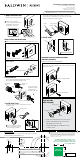
LATCH ASSEMBLY AND INSTALLATION
Install with 1/2" screws.
Snap on collar.
Drive in with hammer.
For Square Corner and Round Corner
Snap together front and back plate.
2. Install chassis
Make sure the slant of latch bolt faces in the direction that the door closes.
1. Adjust and install latch
Measure your door backset as shown.
Entry Knob/Lever Installation Instructions
Fits 1-3/8" (35 mm) up to 2" (51 mm) doors
(Thick door service kits for
2" (51 mm) up to 2-1/2" (64 mm) doors
available through customer service)
www.baldwinhardware.com • Customer Service 1.800.437.7448
interior chassis
Door Preparation
If your door requires drilling, use the supplied template below with the door preparation
instructions available at www.baldwinhardware.com
If backset of door measured
2-3/4" (70mm), adjust latch shown
by grasping the spring pin and
moving it to the 2-3/4" slot.
WARNING: This Manufacturer advises that no lock can provide complete security by itself.
This lock may be defeated by forcible or technical means, or evaded by entry elsewhere
on the property. No lock can substitute for caution, awareness of your environment, and
common sense. Builder’s hardware is available in multiple performance grades to suit the
application. In order to enhance security and reduce risk, you should consult a qualied
locksmith or other security professional.
A
B
Please note: Product
illustrations may differ
from your product.
Installation is the same.
The drilling template must be printed to scale to
ensure correct hole placement. To confirm correct
print scale, the square below must measure exactly
1" by 1" (25mm x 25mm).
1"
25mm
1"
25mm
1"
25mm
Measure
after printing.