
Installation Sheet
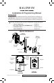

2
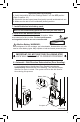
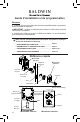
1. Install latch and Strike.
2. Remove cover and battery case.
3. Install Exterior Assembly.
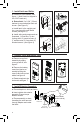
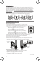
a. Determine your backset, see
gure 1. (Note: Latch is shipped in
the 2-3/8” back set.)
b. Extend bolt. If a 2-3/4” (70mm)
backset is required adjust latch as
shown. (See gure 2).
c. Install latch in the upright posi-
tion, securing with small wood
screws (see gure 3).
d. Install strike and components as
illustrated. 1) Dust Box, 2) rein-
forcing strike, 3) wood screws, 4)
3” wood screws, 5) face plate, 6)
nished screws (see gure 4).
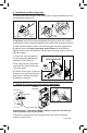
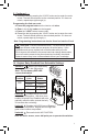
a. Remove cover from
assembly by sliding
cover up and off, see
gure 5.
b. Remove the battery
case from interior as-
sembly by lifting the
case up and out and set
aside, see gure 6.
c. Rotate turnpiece to be
horizontal, see gure 7.
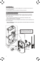
a. Place adapter on door as shown.
b. Insert cylinder into exterior
assembly. Ensure torque
blade is vertical.
c. Place assembly on door,
threading the wire harness
through adapter and under
the latch.
2-3/8"
(60mm)
or
2-3/4"
(70mm)
2-3/4" (70mm)
Adapter
For 2-1/8”
diameter only.
Fig. 7Fig. 6Fig. 5
Fig. 1
Fig. 2
Latch is shown in the
upright position
Top
Fig. 3
Fig. 4
Wire Harness
Cam
Torque Blade
(Shown vertical)
Route wire
under bolt