IMITRE Issue 2 10/05/2000 Mitre Amplifiers Operating Instructions Baldwin Boxall Communications Ltd. Wealden Industrial Estate, Farningham Road Crowborough, East Sussex, TN6 2JR Telephone: 01892 664422 Fax: 01892 663146 Website: www.baldwinboxall.co.uk Email: mail@baldwinboxall.co.
MITRE DESCRIPTION AND SPECIFICATIONS The Mitre range of amplifiers consists of integrated slave and tuner/amplifier models. They are designed to give a high degree of flexibility as well as quality and reliability. Integrated Amplifiers M2000M (Mixer) M2060M (60 Watt), M2120M (120 Watt), M2300M (300 Watt) 1. Four balanced microphone/line universal inputs. 2. Each universal input has the option of cascade priority, phantom power, chime and volume restoration/busy, XLR or screw terminations. 3.
SAFETY IMPORTANT NOTES - DO’S AND DON’TS Ventilation Always ensure adequate ventilation to the amplifier especially the 300 Watt version. Do not obstruct ventilation holes in cover or base. The 300 Watt versions include internal fans that are temperature controlled to prevent overheating, especially if the amplifiers are rack mounted and used for continuous broadcast of music material.
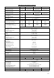
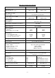
Mitre Integrated Technical Specification Rated output power 100V line 230V AC supply MIXER 60 120 300 N/A 60W 166 Ohms 120W 83 Ohms 300W 33 Ohms THD 1 kHz rated output Aux input 230V AC supply Less than 0.5% typically 0.
Mitre Tuner Specification FM tuning range 87-108 MHz Sensitivity for 40 dB signal to noise ratio (ref. to ±22.5 kHz) 20 dBµ typical IF frequency 10.7 MHz IF rejection @ 98 MHz 70 dB typical Image rejection @ 98 MHz 80 dB typical AM rejection @ 98 MHz 70 dB typical Antenna input impedance 75 Ohms unbalanced AM tuning range 525-1605 kHz Sensitivity for 30 dB signal to noise ratio (ref.
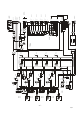
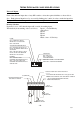
-6- Issue 2 MOUNTED ON PC1180 2 3 3 2 1 1 600uV MIC 80mV LINE INPUT 4 UNIVERSAL MOUNTED ON PC1180 2 3 3 2 1 1 600uV MIC 80mV LINE INPUT 3 UNIVERSAL MOUNTED ON PC1180 2 3 3 2 1 1 600uV MIC 80mV LINE INPUT 2 UNIVERSAL MOUNTED ON PC1180 2 3 3 2 1 1 600uV MIC 80mV LINE INPUT 1 UNIVERSAL 2 3 4 I/P 0V ACCESS 1 2 3 4 I/P 0V ACCESS 6 +24V 4 ACCESS 6 +24V 2 3 4 I/P 0V ACCESS 6 +24V 6 INPUT 5 PHONO INPUT 100mV 3 2 1 5 BUSY 0V 1 I/P 3 2 1 5 BUSY 0V 2 3 0V 1
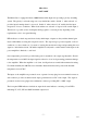
Mitre Slave 120W 300W The Mitre Slave is equipped with two 0dBM balanced line inputs incorporating a priority switching system. The priority is selected using a two-way dual in line switch. Switch ‘1’ when selected ‘on’ provides input 2 muting when 1 is accessed. Switch ‘2’ when selected ‘off’ enables the first input irrespective of access conditions. When both switches are selected ‘on’ input 1 will override input 2.
Mitre Slave Technical Specification Rated output power 100V line 230V AC supply 120W 300W 120W 83 Ohms 300W 33 Ohms THD 1 kHz rated output 230V AC supply Typical output power 1% THD 230V AC supply Less than 0.5% typically 0.
-9- Issue 2 INPUT 2 BALANCED INPUT 500mV INPUT 1 BALANCED INPUT 500mV 3 0V 3 0V 4 2 I/P ACCESS 1 I/P 4 2 I/P ACCESS 1 I/P 0V 0V + - + - 0V INPUT 2 VOLUME 24V AUX SUPPLY OUTPUT 1.
MITRE INTEGRATED AMPLIFIER FEATURES Universal Inputs. Each of the universal inputs has a 6 way DIL switch to select the required facilities as shown below : Note: Each universal input has to be accessed (by linking pins 3 and 4) in order to make the input live. The green LED on the front panel illuminates when an input has been accessed. Priority Selection If priority is set to ‘ON’ then the input will override descending inputs.
Volume Restoration Relay. This relay will energise whenever an input is accessed if the “Vol. Rest / Busy” switch (2) has been selected. The relay contacts can switch either an AC or DC signal providing it does not exceed 100V @ 5A. Here are 3 examples : VOLUME CONTROL 100V AMPLIFIER OUTPUT 50V 0V Example 1: 3 Wire System to Override a Remote Auto Transformer Volume Control. +24V SYSTEM BUSY INDICATOR 0V Example 2: Aux. Busy Indicator.
FLOATING LINE OUTPUT SWITCH 1 2 AFTER MASTER & TONE CONTROLS BEFORE MASTER & TONE CONTROLS CHIME SELECTION SWITCH 3 4 ON OFF NO CHIME OFF OFF ON 1 NOTE CHIME OFF ON 2 NOTE CHIME ON OFF 3 NOTE CHIME ON ON NOTE.
Alarm Tone Generator. The Alarm Tone Generator is configured when dispatched from the factory to produce a 1 second alternating 500 and 900 Hz Dee-Daa sound. However, it is possible to produce pulsed or continuous single frequency tones which could be used for start and stop work, class change, etc. Will remain sounding until access switch removed.
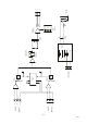
Mitre FM / AM Tuner Amplifier. The tuner provides 7 x FM, 7 x AM (MW) and 1 x Aux. programme. Front Panel View. Rear Panel Time Switch Connections FLOATING LINE OUTPUT CONNECTOR AUX MUTE 0V (GROUND) 1 2 3 4 5 6 STORE SWITCH VIA FRO NT PANEL HOLE CONNECTOR up frequency AM=kH z FM=MHz programme CLOSE TO 0V TO MUTE AUX INPUT / TUNER. USING TIME SWITCH ETC am fm Connect the Time Switch between pin 6 and 0V (pin 3) to mute the Tuner. down programme Tuning a Channel.
VOL REST RELAY 5A 100V MAX 2A MAX 0V +24V MANUFACTURED IN THE UK BY BALDWIN BOXALL COMMUNICATIONS LTD. CROWBOROUGH, E.SUSSEX. TN6 2JR TEL 01892 664422 FAX 01892 663146 +24V DC O/P FUSE SELF RESETTABLE SUPPLY PRESENT FM AM/FM AERIAL AM PUSH O/P 2 0V 1 0dBM FLOATING ALARM LINE O/P 0V ACC BALANCED 0dB OUTPUT 2 BAL O/P 2 PUSH O/P 1 1 2 34 1 2 3 NOTE CHIME ON POWER AMP I/P RLY COIL POST MASTER V/C AUX PRE MASTER V/C MUTE 3 ALARM VOLUME R AUX INPUT PRIORITY 0.
Example Installations With Wiring Diagrams. The following drawings show examples of how to connect amplifiers using the numerous facilities included in them. NB. As supplied from the factory a jumper lead is included on the rear of the M2300. This lead energises the four output relays and enables the user to connect to any of the four zoned outputs. If any output zones are not required the relevant ‘Group Select’ DIL switch should be set to ‘OFF’.
OBTAINING A 600W SINGLE LOUDSPEAKER OUTPUT FIGURE 7 (Page 24) - 1 Zone of 600W Using 2 Slave Amplifiers Shows how two 300W slaves may be configured to produce 600 Watts into a single load. We do not recommend paralleled outputs because both amplifiers would have to possess identical gain and phase throughout the audio frequency range. The two 50V outputs are connected in series to produce 100V to the load and small changes in gain will not cause any problems.
- 18 - Issue 2 GROUP SELECT GROUP ALL 1 12 34 ZONE 2 3 ON MUSIC & PAGING 50V LOUDSPEAKER OUTPUT ZONE1 100V PAGING ONLY 50V LOUDSPEAKER OUTPUT ZONE2 100V MUSIC ONLY 50V LOUDSPEAKER OUTPUT ZONE3 100V M2300M 50V LOUDSPEAKER OUTPUT ZONE4 100V LED INDICATES PRESENCE OF +24V AUX SUPPLY 12 34 AUX DC OUTPUT RESETTABLE FUSE 2A 0V +24V 2A MAX POWER AMPLIFIER INPUT 5 12 34 ON CHIME 2 NOTE 1 NOTE R R CD OR CASSETTE PLAYER L L R L 1 2345 6 3 12 34 5 6 80mV LINE PRIORITY THIS CABL
- 19 - Issue 2 MUSIC & PAGING 50V PAGING ONLY LED INDICATES PRESENCE OF +24V AUX SUPPLY 123 4 AUX DC OUTPUT RESETTABLE FUSE 2A 2A MAX 0V +24V 5 CHIME R R CD OR CASSETTE PLAYER L L R L 4 3 NOTE 1 23 456 3 12 3 456 80mV LINE PRIORITY THIS CABLE SHOULD NOT EXCEED 3 METERS 1 2345 6 CHIME VOLUME ALARM VOLUME POWER AMPLIFIER INPUT 12 34 ON 2 NOTE 1 NOTE CHIME V REST/BUSY 500mV POST MASTER V/C PRE MASTER V/C FLOATING LINE O/P ON 1 2 1 3 6 5 4 SET LINE LEVEL OUT BMS6 2
- 20 - Issue 2 50V ZONE 4 ZONE 3 ZONE 2 ZONE 1 N/C N/O SW FOR MORE INFORMATION PLEASE SEE THE B41R INSTRUCTIONS B41R 4 3 2 1 +24V DIV LED INDICATES PRESENCE OF +24V AUX SUPPLY 2A MAX 0V +24V AUX DC OUTPUT RESETTABLE FUSE 2A 12 3 4 5 CHIME R R CD OR CASSETTE PLAYER L L R L 4 3 NOTE 1 23 4 56 3 1 23 4 5 6 80mV LINE PRIORITY THIS CABLE SHOULD NOT EXCEED 3 METERS 12 3 4 56 CHIME VOLUME ALARM VOLUME POWER AMPLIFIER INPUT 1 2 3 4 ON 2 NOTE 1 NOTE CHIME V REST/BUSY 500m
- 21 - Issue 2 GROUP SELECT GROUP ALL 1 12 34 ON ALL ZONE 2 3 4 +24V ZONE 2 WAREHOUSE 2 50V LOUDSPEAKER OUTPUT ZONE2 100V ZONE 3 OFFICES 50V LOUDSPEAKER OUTPUT ZONE3 100V RELAY OUT ZONE 4 CUSTOMER WAITING AREA PAGE LOCAL VOLUME CONTROL OF MUSIC, OVERRIDE ON PAGE AND ALARM IN 50V LOUDSPEAKER OUTPUT ZONE4 100V 1 23 4 CLOSE TO MUTE AUX INPUT TIME SWITCH.
- 22 - Issue 2 ZONE4 ZONE3 ZONE2 ZONE1 2A MAX 0V +24V 2A MAX 0V +24V 2A MAX 0V +24V 2A MAX 0V +24V 12 3 4 12 3 4 12 3 4 12 3 4 POWER AMPLIFIER INPUT CHIME 5 5 1 2 34 56 5 1 2 34 56 R L 1 2 34 56 CHIME VOLUME ALARM VOLUME R L CHIME VOLUME ALARM VOLUME R L CHIME VOLUME ALARM VOLUME R L 1 2 34 56 CHIME VOLUME ALARM VOLUME 5 1234 ON 2 NOTE 1 NOTE 4 4 4 4 12 34 5 6 3 12 34 5 6 3 12 34 5 6 3 12 34 5 6 3 1 2 34 5 6 80mV LINE PRIORITY CHIME V REST/BUSY 500mV 3
- 23 - Issue 2 3 1 23 4 2 ZO NE ON 4 +24V ALL ZO NE 1 50V LOUD SPEAKE R OU TPUT Z ON E1 100V Z ONE 2 50V LO U DSPEAKER O UTPU T ZO N E2 100V Z ONE 3 50V LO UD SP EAKER O UT PU T ZO NE3 100V LED INDICATES PRESENCE OF +24V AUX SUPPLY ZO NE 4 50V LO U D SPEAKER O U TPU T ZO NE4 100V M2300M M2300S +V +V 2A MAX 0V +24V 1 23 4 ON ON 5 1 2 34 ON C HIME 2 NOTE 1 NOTE 1 2 3 45 6 4 3 NOTE PRE MASTER V/C POST MASTER V/C 2 3 BM S25 1 4 5 6 ON 2 3 6 0V 1 BAL 0V I/P 1
- 24 - Issue 2 600W 16.6 Ohms SERIES OUTPUTS 50V 50V M2300S 300W SLAVE M2300S 300W SLAVE +V 0V +V AUX OUTPUT 0V AUX OUTPUT T2A 24V DC OUTPUT FUSE BOTH OFF T2A 24V DC OUTPUT FUSE 1 2 1 2 ON ON INPUT 2 VOLUME INPUT 2 VOLUME ACC ESS BALANC ED INPUT 0V ACC ESS BALANC ED INPUT 0V FIG 7. OBTAINING A 600W SINGLE LOUDSPEAKER OUTPUT. USING TWO SLAVE AMPLIFIERS.
- 25 - Issue 2 600W 16.
600W 16.
- 27 - Issue 2 FIG 11. +V T2A 24V DC OUTPUT FUSE AUX 24V DC OUTPUT 1.5A MAX TO FEED MIXERS BVMX ETC 0V ON OFF ON ON OFF ON 2 OFF 1 OFF AUX OUTPUT 1 2 ON 1 2 ON 5A 100V MAX VOL REST RELAY 2A MAX 0V +24V 0dBM FLOATING ALARM LINE O/P 0V ACC 3 BAL I/P 0V 1 RLY COIL AUX MUTE 1 2 34 1 2 3 NOTE CHIME ON POST MASTER V/C PRE MASTER V/C POWER AMP INPUT 2 ALARM VOLUME CHIME VOLUME PUSH INPUT4 R L AUX INPUT PRIORITY ON 0V BAL 2 I/P PHANTOM POWER 0.
No4 TO RACK MOUNT M2000, REMOVE 2 x No4 SCREWS, REMOVE 3 x M3 SCREWS AND ALIGN RACK BRACKET. REFIT SCREWS AND REPEAT FOR OTHER SIDE. 2U CODE = M2RACK 3U CODE = M3RACK No4 M3 M3 M3 TO WALL MOUNT M2000, REMOVE 3 x M3 SCREWS AND ALIGN WALL BRACKET. REFIT SCREWS AND REPEAT FOR OTHER SIDE. CODE = MWALL 3 X HOLES FOR MOUNTING TO WALL RECOMENDED SIZE = No10 FIG 12. RACK & WALL MOUNTING ADAPTORS INSERT BRACKETS INTO SLOT IN COVER. (2 OFF) STACK M2000 ON TOP OF BASE UNIT AND INSERT SCREW INTO REAR PANEL.
1 ADDENDUM Please note - The orientation of the six-way plug on pages 10,12 and 14 are reversed. ACCESS CLOSE TO 0V TO ACCESS INPUT. BUSY OPEN COLLECTOR OUTPUT 40V @ 0.5A MAX CLOSES TO 0V WHEN ACTIVE. SEE SWITCH 2 ABOVE. 0V (GROUND) BALANCED SIGNAL INPUT SEE SWITCH 4 ABOVE +24V TO FEED MICROPHONE PRE-AMP, BUSY INDICATORS ETC.