ADJUSTABLE SPEED DRIVE Series 5 Inverter NEMA 4X, IP-65 Installation & Operating Manual 8/01 MN781B
TABLE OF CONTENTS Section Page i. Simplified Operating Instructions . . . . . . . . . . . . . . . . . . . . . . . . . . . . . . . . . . . . . . . . . . 1 ii. Safety Warning . . . . . . . . . . . . . . . . . . . . . . . . . . . . . . . . . . . . . . . . . . . . . . . . . . . . . . . 1 I. Introduction . . . . . . . . . . . . . . . . . . . . . . . . . . . . . . . . . . . . . . . . . . . . . . . . . . . . . . . . . . 2 II. Wiring Instructions . . . . . . . . . . . . . . . . . . . . . . . . . . . . . .
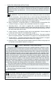
i. SIMPLIFIED OPERATING INSTRUCTIONS IMPORTANT – You must read these simplified operating instructions before proceeding. These instructions are to be used as a reference only and are not intended to replace the detailed instructions provided herein. You must read the Safety Warning below before proceeding. ! WARNING! Disconnect main power when making connections to the control. A.
I. INTRODUCTION The Baldor ID5601-BO Adjustable Speed Drive is a variable speed control in a NEMA-4X / IP65 and watertight enclosure. It is designed to operate 208 - 230 Volt 3-phase AC induction motors through 3.6 Amps RMS. The sine wave coded Pulse Width Modulated (PWM) output, which operates at a frequency of 8 kHz, provides high motor torque, high efficiency and low noise. The control operates from 115 or 208/230 Volt 50/60 Hz single phase AC line input.
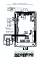
FIGURE 1 – CONTROL L AYOUT (Illustrates Factory Setting of Jumpers and Approximate Trimpot Settings) WHITE ORANGE VIOLET MAIN SPEED POTENTIOMETER (BACK VIEW) MAX CON1 P2 CL P1 FWD R Y STATUS REV J7 POWER B G STOP START/STOP SWITCH (BACK VIEW) BOOST J6 RUN J5 COM LED BOARD RED STOP J4 FIX BOOST ADJ 1X MULT J3 2X 60HZ FREQ 50HZ AUTO 1HP 3/4 1/2 1/4 230V P3 MIN ACCEL DECEL COMP MAN 115V J2 R/F BLACK WHITE NOTES: 1. REV TERMINAL IS USED FOR OPTIONAL FWD-STOP-REV SWITCH. 2.
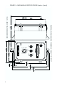
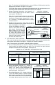
4 [241.96] 9.53 8.82 [224.00] STOP MANUAL AUTO 90 100 0 STOP START STATUS POWER NEMA-4X / IP-65 POWER OFF ON 2.53 [64.35] ADJUSTABLE SPEED DRIVE REVERSE FORWARD 80 10 % SPEED 70 60 20 50 30 40 5.06 [128.59] 5.86 [148.94] RECOMMENDED MOUNTING SCREW: 1/4" (M6) SHOWN WITH OPTIONAL AUTO/MANUAL AND FORWARD-STOP-REVERSE 8.20 [208.17] 0.31 [7.97] 5.51 [139.
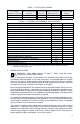
TABLE 1 – ELECTRICAL RATINGS AC Line Input Voltage ±10%, 50/60 Hz (Single Phase Volts AC) Maximum Nominal AC Line Input Current Output Voltage (Amps AC) (Volts AC) Maximum Continuous Output Load Current (RMS Amps/Phase) Maximum Horsepower Rating HP, (kW) 115 16 0 – 230 3.6 1, (0.75) 208/230 10 0 – 230 3.6 1, (0.
TABLE 3 – TERMINAL BLOCK WIRING INFORMATION Designation Connection Supply Wire Gauge (AWG - Cu) Minimum Maximum Maximum Tightening Torque (in-lbs) AC Line Input L1, L2 22 12 12 Motor U, V, W 22 12 12 A. AC Line Connection – Wire the AC line input to L1 and L2 terminals of Terminal Block TB1 as shown in Figure 4. Be sure both Jumpers J1 and J2 are set to the “115V” position for 115 Volt AC line input or to the “230V” position for 208/230 Volt AC line input.
Note: To eliminate the Start/Stop function, connect RUN and COM terminals with the jumper that is provided. See Figure 7, on page 6. CAUTION! Using a jumper to eliminate the Start/Stop function will cause the motor to run at the Main Speed Potentiometer setting when the AC line is applied. F. Voltage Following Connection – An isolated 0 - 5 Volt DC analog signal can also be used to control motor speed. See Figure 8.
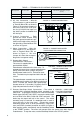
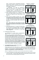
fault). To set the control to automatically reset after a fault has been cleared, set Jumper J3 to the "AUTO" position. See Figure 12. (Also see section VIB, on page 9 and Table 4, on page 10.) WARNING! The motor will automatically restart when the AC line is applied, if Jumper J4 is set to the "AUTO" or “MAN” position and the Start/Stop Switch is eliminated with a jumper installed between the RUN and COM terminals. FIGURE 12 – RESTART MODE SELECTION J4 Set for Manual Reset Mode (Factory Setting) ! D.
B. The hi-pot tester must have an automatic ramp-up to the test voltage and an automatic ramp-down to zero voltage. Note: If the hi-pot tester does not have automatic ramping, then the hi-pot output must be manually increased to the test voltage and then manually reduced to zero. This procedure must be followed for each machine to be tested. A suggested hi-pot tester is Slaughter Model 2550. WARNING! Instantaneously applying the hi-pot voltage will cause irreversible damage to the speed control. ! C.
TABLE 4 – FAULT RECOVERY & RESETTING THE CONTROL* Auto Mode Manual Mode Auto or Manual Mode with Start/Stop Switch Installed with Start/Stop Switch Installed with Start/stop Switch Removed Fault Undervoltage Control will automatically reset. Reset the control with the Start/Stop Switch. Control will automatically reset. Overvoltage Control will automatically reset. Reset the control with the Start/Stop Switch. Control will automatically reset. Short Circuit Control will automatically reset.
FIGURE 20 more rapid deceleration time, rotate the DECEL trimpot counterclockwise. For longer deceleration time, rotate the DECEL DECEL TRIMPOT RANGE trimpot clockwise. See Figure 20. 5 Note: To provide increased resolution of the ACCEL and DECEL trimpots, 50% rotation covers 0.3 - 5 seconds. 2.5 Application Note: On applications with high inertial loads, the deceleration may automatically increase in time.
The CL trimpot is factory set for 160% of Jumper J3 range setting. For a higher current limit setting, rotate the CL trimpot clockwise. For a lower current limit setting, rotate the CL trimpot counterclockwise. The current limit also contains I2t trip function. The control will trip according to a predetermined current vs. time function. The trip curve is directly related to the CL set point and can be changed with the CL trimpot. See Figure 23 on page 11.
IX. DIAGNOSTIC LEDs The motor control is designed with LEDs mounted on the front cover to display the control’s operational status. A. Power On (ON) – Indicates the presence of bus voltage. B. Status (STATUS) – The Status LED is a tricolor LED that provides indication of the control’s operational status including installation problems such as incorrect input voltage, overvoltage, undervoltage and control miswiring.
XI. LIMITED WARRANTY For a period of 2 years from date of original purchase, BALDOR will repair or replace without charge controls which our examination proves to be defective in material or workmanship. This warranty is valid if the unit has not been tampered with by unauthorized persons, misused, abused, or improperly installed and has been used in accordance with the instructions and/or ratings supplied. This warranty is in lieu of any other warranty or guarantee expressed or implied.