
Electric Company Computer Drive User Manual


www.supportme.net
Input / Output 5-23MN1942
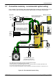
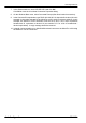
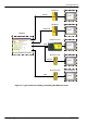
5.7 Connection summary - recommen d ed system wiring
As an example, Figure 40 shows the recommended wiring necessary for the MicroFlex e100 to
control a motor, while conforming to the EMC requirements for ‘industrial’ environments.
2A
PC
AC power
Motor power U V W
Control circuit s upply (fused).
Use twisted pair cable with a
ferrite sleeve (see s ection 3.4.8).
Motor
+24VDC
H The M icroFlex e100 should be mounted on an earthed metal backplane.
H Ens ure cables do not obstruct airflow to the heatsink.
H Motor represents a typical Baldor BSM motor. Linear motors may also be c ontrolled by MicroFlex e100.
H Conductive shield earth/ground cl amps are not supplied.
H When using single phase supplies i t may be necessary to reverse the A C power filter - see section 3.4.7.2.
0V
Filter
L1
L2
L1
L2
L3
Star
point
L1
L2
L3
Optional
regen
resistor
(Dynamic
brake)
L3
Connect motor power cable
shield to metal backplane using
conducti ve shield clamp
PE
From
fuses
AC power in
Motor feedback
Regen
Shielded twisted pair, clamped to
metal back plane near drive using
conductive shield earth/ground
clamp (see sections 3.6 and C.1.6).
Connect AC power cable shield to
metal back plane using conductive
shiel d clamp (see section C.1.6).
Motion controller
Drive enable
input
+24VDC 0V
Ethernet
USB
Ferrite
Figure 40 - Recommended system wiring