
Electric Company Computer Drive User Manual

www.supportme.net
5-18 Input / Output MN1942
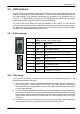
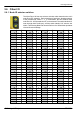
H The maximum bus length depends on the bit-timing
configuration (baud rate). The table opposite shows
the approximate maximum bus length (worst-case),
assuming 5ns/m propagation delay and a total
effective device internal in-out delay of 210ns at
1Mbit/s, 300ns at 500 - 250Kbit/s, 450ns at 125Kbit/s
and 1.5ms at 50 - 10Kbit/s.
(1)
For bus lengths greater than about 1000m,
bridge or repeater devices may be needed.
H The compromise between bus length and CAN baud
rate must be determined for each application. The
CAN baud rate can be set using the BUSBAUD keyword. It is essential that all nodes on the
network are configured to run at the same baud rate.
H The wiring topology of a CAN network should be as close as possible to a single line/bus
structure. However, stub lines are allowed provided they are kept to a minimum (<0.3m at
1Mbit/s).
H The 0V connection of all of the nodes on the network must be tied together through the CAN
cabling. This ensures that the CAN signal levels transmitted by MicroFlex e100 or CAN
peripheral devices are within the common mode range of the receiver circuitry of other nodes
on the network.
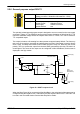
5.5.2.1 Opto-isolation
On the MicroFlex e100, the CAN channel is opto-isolated. A voltage in the range 12-24V must
be applied between pin 9 (+24V) and pin 3 or 6 (0V) of the CAN connector. From this supply, an
internal voltage regulator provides the 5V at 100mA required for the isolated CAN circuit. CAN
cables supplied by Baldor are ‘category 5’ and have a maximum current rating of 1A, so the
maximum number of MicroFlex e100 units that may be used on one network is limited to ten.
5.5.3 CANopen
Baldor have implemented a CANopen protocol in Mint (based on the ‘Communication Profile’ CiA
DS-301) which supports both direct access to device parameters and time-critical process data
communication. The MicroFlex e100 complies with CANopen slave device profile DS402, and
can be a DS401 or DS403 master device (with limited functionality). It is able to support and
communicate with a variety of devices including:
H Any third party digital and analog I/O device that is compliant with the ‘Device Profile for
Generic I/O Modules’ (CiA DS-401).
H Baldor HMI (Human Machine Interface) operator panels, which are based on the ‘Device
Profile for Human Machine Interfaces’ (DS403).
H Other Baldor controllers with CANopen support for peer-to-peer access using extensions to
the CiA specifications (DS301 and DS302).
The functionality and characteristics of all Baldor CANopen devices are defined in individual
standardized (ASCII format) Electronic Data Sheets (EDS) which can be found on the Baldor
Motion Toolkit CD supplied with your product, or downloaded from www.supportme.net
.
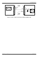
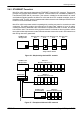
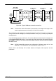
Figure 38 shows a typical CANopen network with a NextMove e100 manager node, one
MicroFlex e100 slave node and a Baldor HMI operator panel:
CAN Maximum
Baud Rate Bus Length
1Mbit/s 25m
500Kbit/s 100m
250Kbit/s 250m
125Kbit/s 500m
100Kbit/s 600m
50Kbit/s 1000m
20Kbit/s 2500m
(1)
10Kbit/s 5000m
(1)