
Electric Company Computer Drive User Manual

www.supportme.net
5-16 Input / Output MN1942
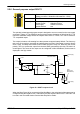
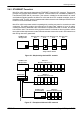
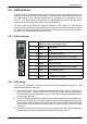
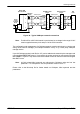
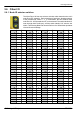
5.4.3 Ethernet connectors
Ethernet connections are made using the identical RJ45 Ethernet receptacles.
Location
E1 & E2
Pin Name Description
1 TX+ Transmit+
2 TX- Transmit-
3 RX+ Receive+
4 - (NC)
5 - (NC)
6 RX - Receive-
7 - (NC)
8 Shield Shield connection
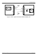
To connect the MicroFlex e100 to other EPL devices, ordinary shielded CAT5 Ethernet cables
are used. Cables may be up to 100m (328 ft) long. Two varieties of CAT5 cable are available;
‘straight’ or ‘crossed’. S traight cables have the TX pins of the connector at one end of the cable
wired to the TX pins of the RJ45 connector at the other end of the cable. Crossover cables have
the TX pins of the connector at one end of the cable wired to the RX pins of the RJ45 connector
at the other end of the cable.
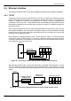
Provided the network consists of only Baldor EPL controllers and drives (and any hub), straight
or crossed cables may be used. This is because many Ethernet devices, including hubs and all
Baldor EPL products, incorporate Auto-MDIX switching technology which automatically
compensates for the wiring of the straight cable. However, if other manufacturer’s EPL nodes are
included in the network, crossover cables should be used as recommended by the ETHERNET
Powerlink S tandardization Group (EPSG).
The MicroFlex e100 Ethernet interface is galvanically isolated from the rest of the MicroFlex e100
circuitry by magnetic isolation modules incorporated in each of the Ethernet connectors. This
provides protection up to 1.5kV. The connector/cable screen is connected directly to the chassis
earth of the MicroFlex e100. Termination components are incorporated in each of the Ethernet
connectors, so no further termination is required.
The EPL network supports the 100Base-TX (100Mbit/s) system only, so attempting to connect
slower 10Base-T (10Mbit/s) nodes will cause a network error.
1
8