
Electric Company Computer Drive User Manual


www.supportme.net
Feedback 4-5MN1942
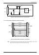
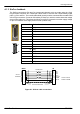
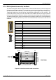
4.1.1.4 Encoder cable pin configuration - Baldor linear motors
Baldor linear motors use two separate cables (encoder and Hall). The cores of these two cables
must be wired to the appropriate pins of the 15-pin D-type mating connector (supplied):
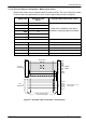
Signal name
MicroFlex e100
X8 pin
Encoder cable internal wire colors
CHA+ 1
CHA- 9
CHB+ 2
Please refer to MN1800 Linear Motors
CHB- 10
P
l
e
a
s
e
r
e
f
e
r
t
o
M
N
1
8
0
0
L
i
n
e
a
r
M
o
t
o
r
s
Installation & Operating Manual for details.
CHZ+ 3
CHZ- 11
Baldor Hall cable internal wire colors
Hall U+ 6 White
Hall V+ 8 Red
Hall W+ 15 Black
+5V out 12 Brown
Hall GND 13 Green
CHA+
CHA-
CHB+
CHB-
+5V
DGND
1
9
2
10
3
11
12
X8
Encoder
Feedback
CHZ+ (INDEX)
CHZ- (INDEX)
6
5
15
14
8
7
13
Hall U+
Hall U-
Hall W+
Hall W-
Hall V+
Hall V-
4 Sense
Hall
Feedback
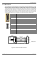
Connect overall shield to
connector backshells.
Twisted pairs
Leave pins 5, 7 & 14
unconnected
Motor
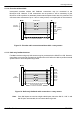
Figure 17 - Encoder cable connections - linear motors