
Electric Company Computer Drive User Manual


www.supportme.net
Feedback 4-3MN1942
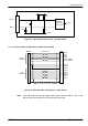
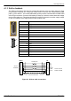
Hall U-
Hall U+
MicroFlex e100
MAX3096
Differential
line receiver
to CPU
+5V
1nF
1nF
DGND
6
5
2k2 10k
4k7
Figure 13 - Hall channel input circuit - U phase shown
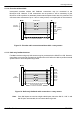
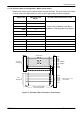
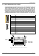
4.1.1.1 Encoder cable configuration - Baldor rota ry motors
CHA+
CHA-
CHB+
CHB-
+5V out
DGND
1
9
2
10
3
11
12
X8
CHZ+ (INDEX)
CHZ- (INDEX)
6
5
15
14
8
7
13
Hall U+
Hall U-
Hall W+
Hall W-
Hall V+
Hall V-
4 Sense
Hall
Feedback
Connect overall s hield
to connector backshells.
Twisted pairs
Encoder
Feedback
Motor
Figure 14 - Encoder cable connections - rotary motors
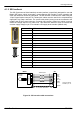
Note: If the Hall inputs are used as single ended inputs, leave the Hall U-, Hall V- and
Hall W- pins unconnected; do not connect them to ground.