
Electric Company Computer Drive User Manual


www.supportme.net
3-22 Basic Installation MN1942
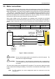
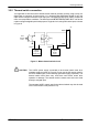
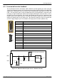
3.5.6 Motor brake connection
You might wish to wire a motor’s brake, via relays, to digital outputs on connector X3 (see section
3.3.1). This provides a way for the MicroFlex e100 to control the motor’s brake. A typical circuit
is shown in Figure 10.
C
D
from motor brake
connecti ons
Separate
customer
suppli ed
24VDC supply
Relay 2
Relay 1
+24VDC 0V
The inner shield
surrounding the
brake wires should
be earthed/grounded
at one point only.
The relays have normally open
contacts and are s hown deactivated
(contacts open, brake engaged).
DOUT0+
DOUT0-
11
1
DOUT1+
DOUT1-
13
3
User supply V+
User supply GND
‘X3’
Figure 10 - Motor brake control circuit
This circuit uses the drive enable signal (configured using DRIVEENABLEOUTPUT to appear on
DOUT0) in conjunction with DOUT1 (configured as the MOTORBRAKEOUTPUT). See the Mint help
file for details. With this configuration, the following sequences can be used to control the brake.
To engage the brake:
H The motor is brought to rest under normal control;
H Relay 2 is deactivated, causing the brake to engage;
H The drive is disabled. This removes power from the motor and causes Relay 1 to be
deactivated.
To disengage the brake:
H The drive is enabled, activating Relay 1;
H Power is applied to the motor to hold position under normal control;
H Relay 2 is activated, causing the brake to be disengaged.
It may be necessary to include a small delay, after Relay 2 has been activated, before starting
motion. This delay will allow time for the relay contacts to engage and the brake to release.
CAUTION: The 24VDC power supply used to power the brake must be a separate
supply as shown in Figure 10. Do not use the supply that is powering the
MicroFlex e100 digital outputs. The brake wires often carry noise that could
cause erratic drive operation or damage. The brake contacts must never be
wired directly to the digital outputs. The relay(s) should be fitted with a
protective flyback diode, as shown. The separate 24VDC supply used for the
motor brake may also be used to power the relay in the thermal switch circuit
(section 3.5.5).