
Electric Company Computer Drive User Manual


www.supportme.net
Basic Installation 3-21MN1942
3.5.5 Thermal switch connection
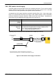
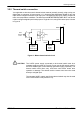
You might wish to wire the motor’s thermal switch contacts (normally closed), using a relay, to a
digital input on connector X3 (see section 3.3.1). Using the Mint WorkBench Digital I/O tool, the
input can be configured to be the motor trip input. This allows the MicroFlex e100 to respond to
motor over-temperature conditions. The Mint keyword MOTORTEMPERATUREINPUT can also be
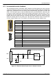
used to configure a digital input for this purpose. A typical circuit, using DIN1 as the input, is shown
in Figure 9.
A
B
motor
thermal
switch
Relay
Customer
suppli ed
24VDC
supply
+24VDC 0V
Separate
customer
suppli ed
24VDC supply
+24VDC 0V
DIN1+
DIN1-
16
6
‘X3’
Figure 9 - Motor thermal switch circuit
CAUTION: The 24VDC power supply connected to the thermal switch must be a
separate supply as shown in Figure 9. Do not use the 24V supply used for
the drive enable signal, or the internally generated supply (if present). The
thermal switch wires often carry noise that could cause erratic drive
operation or damage. The thermal switch contacts must never be wired
directly to a digital input.
The separate 24VDC supply used for the thermal switch may also be used
for the motor brake circuit (section 3.5.6).