
Electric Company Computer Drive User Manual

www.supportme.net
Basic Installation 3-13MN1942
3.4.3 Input power conditioning
Certain power line conditions must be avoided; an AC line reactor, an isolation transformer or a
step up/step down transformer may be required for some power conditions:
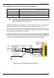
H If the feeder or branch circuit that provides power to the MicroFlex e100 has permanently
connected power factor correction capacitors, an input AC line reactor or an isolation
transformer must be connected between the power factor correction capacitors and the
MicroFlex e100 to limit the maximum symmetrical short circuit current to 5000A.
H If the feeder or branch circuit that provides power to the MicroFlex e100 has power factor
correction capacitors that are switched on line and off line, the capacitors must not be
switched while the drive is connected to the AC power line. If the capacitors are switched on
line while the drive is still connected to the AC power line, additional protection is required.
A Transient V oltage Surge Suppressor (TVSS) of the proper rating must be installed
between the AC line reactor (or isolation transformer) and the AC input to the
MicroFlex e100.
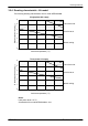
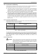
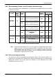
3.4.3.1 Input power-cycling and inrush
If AC power has been removed from the MicroFlex e100, it should remain disconnected for the
period specified in Table 1, before it is reapplied.
MicroFlex e100
current rating
Minimum power cycle delay period
(seconds)
3A 25
6A 45
9A 65
Table 1 - Power cycle intervals
This delay allows the input surge protection circuit to perform correctly, ensuring that the inrush
current (typically 1.7A) is below the drive rated current. Power-cycling the drive more frequently
could cause high inrush current and corresponding nuisance operation of circuit breakers or
fuses. Repeated failure to observe the delay period could reduce the lifetime of the
MicroFlex e100.
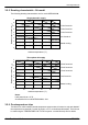
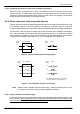
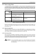
3.4.3.2 Discharge period
DANGER: After AC power has been removed from the MicroFlex e100, high voltages
(greater than 50VDC) can remain on the regeneration resistor connections
until the DC-bus circuitry has discharged. The high voltage can remain for
the period specified in Table 2.
MicroFlex e100
current rating
Time for DC-bus to discharge to 50V or less
(maximum, seconds)
3A 83
6A 166
9A 248
Table 2 - DC-bus discharge periods