
Electric Company Computer Drive User Manual

www.supportme.net
Basic Installation 3-9MN1942
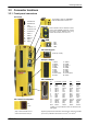
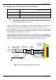
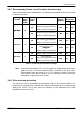
3.3 Connector location s
3.3.1 Front panel connectors
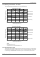
11 Status+
12 DGND
13 DOUT1+
14 DIN2+
15 DGND
16 DIN1+
17 DIN0+
18 DGND
19 Drive enable+
20 Shield
1 (NC)
2 Data-
3 Data+
4GND
(Currently unused)
X3 Input / Output
X6 Auxiliary port
USB
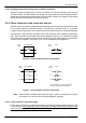
X8 Feedback In
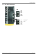
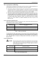
X1 Power
Earth/Ground
Earth/Ground
(NC)
L1 AC Phase 1 / L
L2 AC Phase 2 / N
L3 AC Phase 3
U Motor U
V Motor V
W Motor W
R1 Regen
R2 Regen
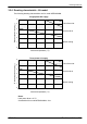
Pin Incremental SinCos SSI EnDat
1 CHA+ (NC) Data+ Data+
2 CHB+ (NC) Clock+ Clock+
3 CHZ+ (NC) (NC) (NC)
4 Sense Sense Sense Sense
5HallU-Sin- (NC) Sin-*
6HallU+Sin+ (NC) Sin+*
7HallV-Cos- (NC) Cos-*
8HallV+Cos+(NC) Cos+*
9 CHA- (NC) Data- Data-
10 CHB- (NC) Clock- Clock-
11 CHZ- (NC) (NC) (NC)
12 +5V out +5V out +5V out +5V out
13 DGND DGND DGND DGND
14 Hall W- (NC) (NC) (NC)
15 Hall W+ (NC) (NC) (NC)
Shell Shield Shield Shield Shiel d
1 Status-
2DGND
3DOUT1-
4DIN2-
5DGND
6DIN1-
7DIN0-
8DGND
9 Drive enable-
10 Shield
0V
+24V
X2 Control circuit power
* EnDat v2.1 only. EnDat v2.2 does not use the Sin and
Cos signals.
Node ID
These swi tches set the MicroFlex e100’s
node ID for ETHERNET Powerli nk, and the
final value of the IP address when using
TCP/IP. See sections 5.6.1 and 6.2.4.
(NC) = Not Connected. Do not
make a connection to this pi n.
LEDs
The STATUS, CAN and ETHERNET
LEDs are described in section 7.2.1.
Tightening torque for terminal bl ock connections (X1 & X 3) is 0.5-0.6Nm
(4.4-5.3 lb-in). Maximum wire sizes: X1: 2.5mm
2
; X3: 0.5mm
2
.